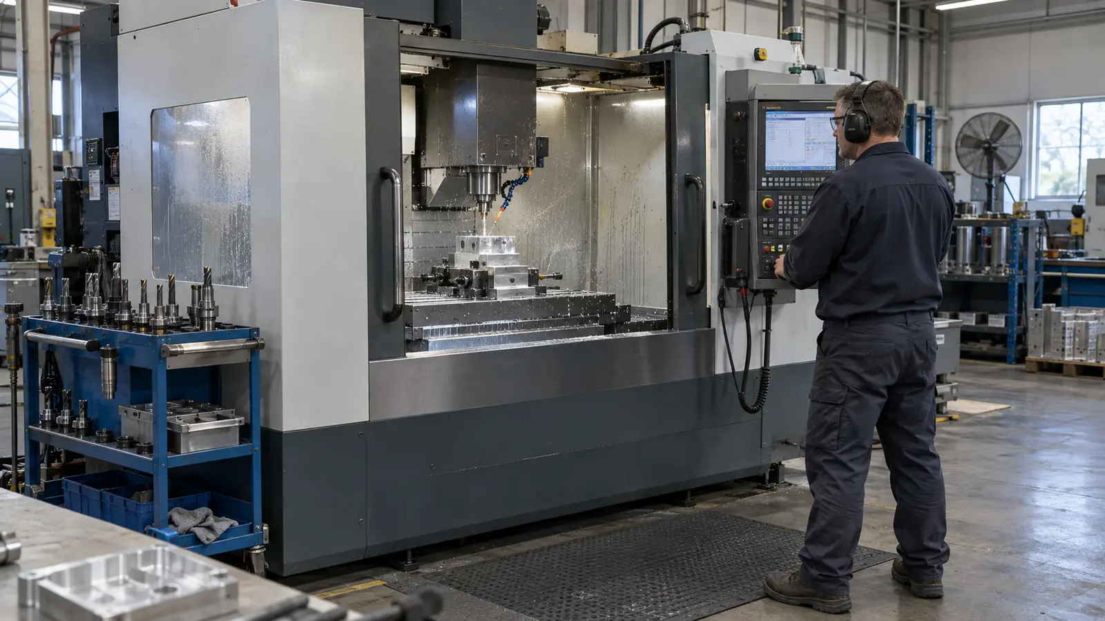
A 3-axis CNC machine moves a cutting tool along the X, Y and Z linear axes to mill, drill and contour a fixed workpiece.
It is usually the lowest-cost CNC option for prismatic parts whose critical features are accessible from one or two directions.
A 3-axis CNC machine is a computer-controlled machining system that moves a cutting tool along three linear axes, X (left to right), Y (front to back), and Z (up and down), to remove material from a stationary workpiece. It is the most widely used CNC platform in manufacturing, responsible for producing the majority of milled, drilled, and contoured metal and plastic parts across industries worldwide.
Despite the growing adoption of 4-axis and 5-axis systems, 3-axis CNC machining remains the dominant platform for parts with prismatic geometry, flat surfaces, pockets, holes, and simple contours. According to Mordor Intelligence, three-axis machining centers accounted for approximately 40.74% of global CNC machine revenue in 2025, favored by job shops and contract manufacturers producing prismatic parts at scale. The global CNC machine market itself reached an estimated USD 74.82 billion in 2025 and is projected to grow to USD 105.7 billion by 2031.
Its combination of proven accuracy (0.01 mm per ISO 2768), low operating cost, fast setup, and wide availability makes 3-axis CNC the most practical choice for the majority of production and prototyping work. This guide covers everything engineers, sourcing managers, and product designers need to know: how 3-axis machines work, what they can and cannot do, programming and workholding fundamentals, tolerances and surface finishes, compatible materials, cost context, DFM rules, real-world part examples, comparison to multi-axis systems, and how to decide when 3-axis is the right choice for your project.
Key takeaways
- 3-axis CNC is best for flat surfaces, pockets, slots, holes and 2.5D contours.
- One to three setups are typical; every repositioning step adds time and alignment risk.
- Meco's published machining reference reaches ±0.01 mm, with CMM inspection verified to ±0.002 mm.
- Use 4-axis or 5-axis machining when multi-face accuracy, compound angles or undercuts make repeated setups inefficient.
- Send a STEP or IGES file, drawing, material, volume, finish and inspection requirements for an accurate quote.
How Does a 3-Axis CNC Machine Work?
A 3-axis CNC machine operates by translating a digital part design into physical cutting tool movements along three perpendicular axes. The X-axis controls left-to-right motion, the Y-axis controls front-to-back motion, and the Z-axis controls spindle depth (up and down). The cutting tool, typically an end mill, drill bit, or face mill, rotates at high speed in the spindle while the machine moves the tool or the worktable (depending on the configuration) to remove material according to the programmed toolpath.
The workpiece is clamped to the machine table in a fixed position. Because the tool can only approach the workpiece from above (or from a single orientation per setup), all features must be accessible from that direction. If machining is required on multiple faces, the operator must manually unclamp, reposition, and re-indicate the workpiece. This process is called a "setup" or "op" (operation). Most 3-axis parts require between one and three setups to complete all features.
Step-by-Step: From CAD File to Finished Part
Step 1, CAD Design: The part geometry is created in 3D CAD software such as SolidWorks, Fusion 360, or CATIA. The engineer defines all dimensions, tolerances per ISO 2768 or ASME Y14.5 GD&T, material specification, and surface finish requirements on the engineering drawing.
Step 2, CAM Programming: The CAD model is imported into CAM software, which generates the toolpath: the precise sequence of cutting tool movements. The programmer selects cutting strategies (face milling, pocket milling, drilling, contouring), tools, spindle speeds, feed rates, and depths of cut. The CAM software outputs G-code, the machine-readable instruction set that controls every axis movement.
Step 3, Machine Setup: The operator loads the G-code into the CNC controller, mounts the raw stock (billet, plate, or blank) onto the machine table using a vise, clamps, or custom fixture, installs the first cutting tool in the spindle, and sets the work coordinate origin (datum). Proper workholding is critical at this stage, as the fixturing method directly affects dimensional accuracy and surface finish quality.
Step 4, Machining: The CNC controller executes the G-code line by line. The spindle rotates the cutting tool while the machine moves along X, Y, and Z axes simultaneously to produce the programmed geometry. Coolant (flood, mist, or through-spindle) is applied to manage heat, lubricate the cut, and evacuate chips from the cutting zone.
Step 5, Inspection and Post-Processing: The machined part is measured against the drawing using calipers, micrometers, or a CMM (coordinate measuring machine). If the part requires secondary operations, such as surface finishing, heat treatment, or mechanical assembly, it proceeds to the next production stage.
What Can a 3-Axis CNC Machine Do?
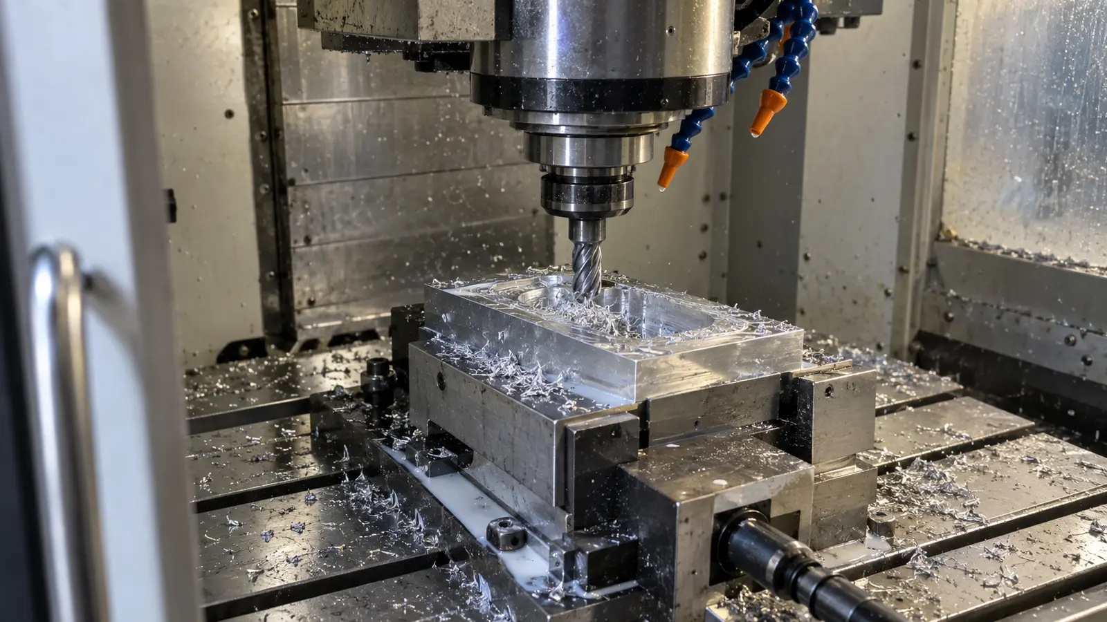
A 3-axis CNC machine can perform a wide range of subtractive manufacturing operations on metals and plastics. The primary operations include face milling (producing flat surfaces), pocket milling (creating recessed cavities), slot milling (cutting channels and grooves), contour milling (following curved 2D profiles), drilling (through-holes and blind holes), boring (enlarging existing holes to precise diameters), tapping (cutting internal threads), and engraving (surface text or markings).
The key geometric constraint is that all features must be accessible from the tool's approach direction, typically the top face of the workpiece. This means 3-axis CNC excels at what machinists call "2.5D geometry": parts that have complex 2D profiles but relatively simple depth variation. A mounting bracket with pockets, holes, and chamfers on its top face is a textbook 3-axis part. A turbine blade with compound curves on every surface is not.
Typical Parts Suited to 3-Axis CNC Machining
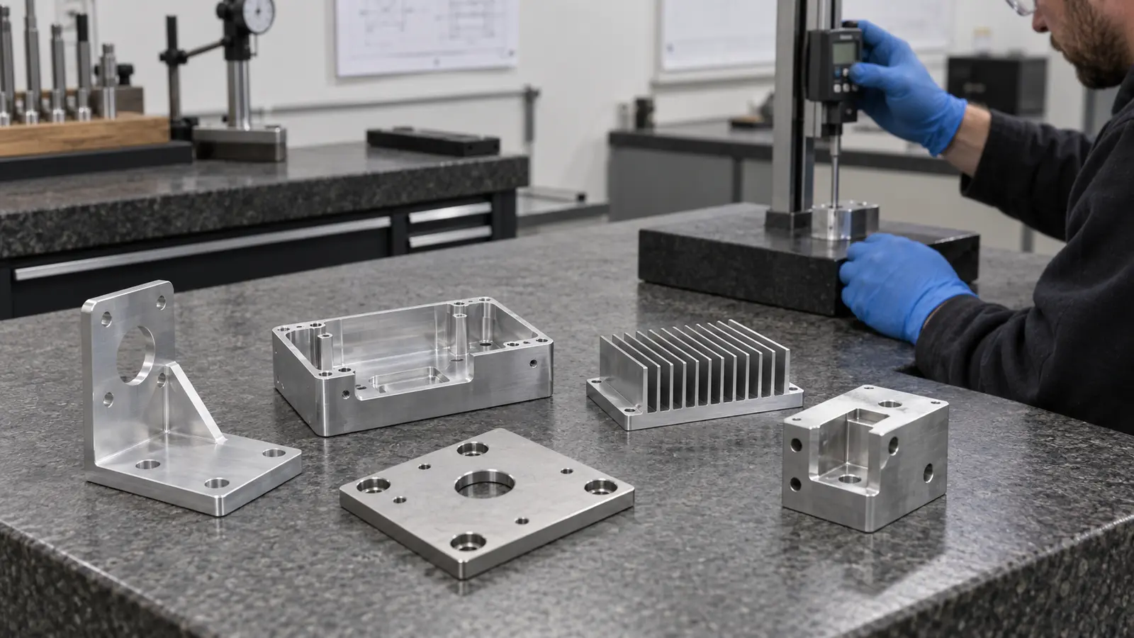
Mounting brackets and flanges, electronics enclosures and housings, adapter plates and interface blocks, heat sinks with straight fin geometry, mold cavities and cores for injection molding, connector blocks, jigs and fixtures, gearbox covers, sensor mounts, and any prismatic part with features primarily on one or two faces.
How 3-Axis CNC Programming Works
3-axis CNC programming is the process of generating the G-code instructions that control the machine's movements. G-code is a standardized language (defined by ISO 6983) consisting of alphanumeric commands that tell the machine where to move (coordinates), how fast to move (feed rate), how fast to spin the tool (spindle speed), and which tool to use (tool number). Common G-code commands for 3-axis milling include G00 (rapid positioning), G01 (linear interpolation at a specified feed rate), G02/G03 (circular interpolation for arcs), and G81-G89 (canned drilling cycles).
In modern manufacturing, almost all G-code is generated automatically by CAM (Computer-Aided Manufacturing) software rather than written by hand. The programmer imports the CAD model, selects the machining operations, defines cutting parameters (speeds, feeds, depths of cut, stepover distances), and the CAM software calculates the toolpath and outputs the corresponding G-code. Leading CAM platforms used for 3-axis programming include Fusion 360, Mastercam, SolidCAM, and Siemens NX CAM.
The relative simplicity of 3-axis programming, compared to the rotary-axis collision avoidance and tool-vector calculations required for 4-axis and 5-axis work, is one of the primary reasons 3-axis machining remains cost-effective. Programming time is shorter, the risk of programming errors is lower, and the operator skill level required to verify and run the program is standard rather than specialist-level.
Workholding and Fixturing for 3-Axis CNC
Workholding is how the raw material is secured to the machine table during cutting. It is one of the most important variables in 3-axis CNC machining because poor fixturing causes vibration (chatter), part movement, dimensional inaccuracy, and poor surface finish. The three most common workholding methods for 3-axis CNC are described below.
Machine vise: The most common workholding device for 3-axis CNC milling. A precision vise clamps the workpiece between two hardened jaws, with the fixed jaw providing the datum reference. Standard 6-inch vises handle most small-to-medium parts. For production runs, dual-station or multi-station vises allow multiple parts to be loaded simultaneously, reducing load/unload time per cycle.
Clamps and T-slot fixtures: For parts that are too large for a vise, or that require access to features the vise jaws would obstruct, step clamps, strap clamps, and toe clamps bolt directly into the machine table's T-slots to hold the workpiece. This method offers more flexibility in part positioning but requires more setup time.
Custom fixtures: For production runs where setup time and repeatability are critical, custom-machined fixtures (sometimes called "soft jaws" or "dedicated fixtures") are designed to match the exact geometry of the part. These fixtures locate the part precisely, reduce operator setup time, and ensure consistent positioning across hundreds or thousands of parts. At Meco, fixture design is included as part of our standard R&D engineering and DFM workflow.
The general principle governing all 3-axis fixturing is the 3-2-1 locating rule: three points define the primary datum plane (preventing movement in one axis), two points define the secondary plane, and one point defines the tertiary. This fully constrains the workpiece in all six degrees of freedom and forms the foundation of repeatable, accurate CNC workholding.
Common Types of 3-Axis CNC Machines
The term "3-axis CNC machine" encompasses several distinct machine types, each optimized for different materials, part sizes, and production environments. Understanding the differences is important when specifying parts or selecting a manufacturing partner.
| Machine Type | Description | Materials | Best For |
|---|---|---|---|
| Vertical Machining Center (VMC) | Vertical spindle, enclosed work area, automatic tool changer (ATC), flood coolant system. The workhorse of production CNC milling. Brands include Haas, Mazak, and DMG Mori. | Aluminum, steel, stainless steel, titanium, brass, engineering plastics | Production parts, mold making, precision components, high-volume programs |
| CNC Milling Machine (Knee Mill) | Vertical or horizontal spindle, manual or semi-automatic tool change. Simpler, smaller, and less expensive than a VMC. | All metals and plastics | Job shops, small-batch work, prototyping, educational settings |
| CNC Router | Gantry-style frame, high-speed spindle, large work envelope (often 4×8 ft or larger). Lighter construction than a mill. | Wood, plastic, foam, composites, soft aluminum | Sign making, woodworking, furniture manufacturing, large-format sheet cutting |
| CNC Engraving Machine | High-speed spindle (30,000+ RPM), small tools, fine-detail capability, low cutting forces. | Soft metals, plastics, wood | Engraving, nameplate production, mold texturing, jewelry |
| Bed-Type Mill | Fixed table (no Y-axis saddle), spindle head moves in all three axes. Extremely rigid due to full-width bed support. | Steel, cast iron, heavy alloys | Heavy-duty machining, large parts, long production runs |
For industrial contract manufacturing, the environment where most OEM parts are produced, the vertical machining center is the dominant 3-axis platform. It combines automatic tool changing, enclosed coolant management, rigid construction, and programmable repeatability. Meco operates VMC-class 3-axis CNC equipment with a work envelope of 1016 x 508 x 635 mm, supporting production runs from single prototypes to millions of parts. For details on our full machining capabilities, see our custom CNC machining services page.
3-Axis vs. 4-Axis vs. 5-Axis CNC Machining: Key Differences
The number of axes on a CNC machine determines the geometric complexity it can produce, the number of setups required, and the cost per part. Understanding when to use 3-axis versus multi-axis machining is one of the most important decisions in part design and sourcing.
| Factor | 3-Axis CNC | 4-Axis CNC | 5-Axis CNC |
|---|---|---|---|
| Axes of Motion | X, Y, Z (linear) | X, Y, Z + A (single rotary) | X, Y, Z + A, B (two rotary, simultaneous) |
| Geometric Capability | 2D and 2.5D: flat surfaces, pockets, holes, simple contours | Multi-sided parts, cylindrical features, angled holes, peripheral engraving | Organic contours, deep pockets, compound angles, undercuts, complex overhangs |
| Setup Requirement | 1 to 3 setups per part (manual repositioning) | Fewer setups (rotary indexing reduces flipping) | Single setup ("Done-in-One") |
| Accuracy (ISO 2768) | ±0.01 mm standard | ±0.01 mm with improved repeatability | ±0.005 mm ultra-precision |
| Programming Complexity | Straightforward CAM, standard G-code | Moderate, requires rotary axis collision avoidance | Advanced, requires simultaneous 5-axis CAM software |
| Machine Cost (Industrial VMC) | $50,000 to $150,000 | $75,000 to $250,000 | $150,000 to $500,000+ |
| Cost Per Part | Lowest (best for volume production) | Moderate | Highest (justified only by part complexity) |
| Best Industries | Automotive, electronics, hardware, industrial, general manufacturing | Medical tools, robotics, fluid systems, automotive | Aerospace, defense, medical implants, turbine/energy |
| Operator Skill Level | Standard CNC training | Intermediate | Specialist-level programming and setup |
If the part has features on three or more faces that must hold positional accuracy relative to each other, 4-axis CNC machining reduces setups and improves repeatability. Our in-depth analysis of why 4-axis CNC is powering North America covers the specific cost and throughput advantages in detail. If the part has organic surfaces, compound angles, deep undercuts, or requires single-setup completion for quality or throughput reasons, 5-axis CNC machining is the right platform. For a complete technical breakdown of simultaneous vs. positional 5-axis motion, see our guide on what is 5-axis CNC machining.
How 3-Axis CNC Compares to 4-Axis and 5-Axis in Practice
The comparison table above captures the specifications, but the real decision between axis configurations happens on the shop floor, where geometry, setup count, and total cycle cost intersect. Each platform solves a different production problem, and understanding those practical trade-offs prevents both over-engineering (paying for capability you do not need) and under-engineering (forcing a 3-axis machine to do work that belongs on a multi-axis platform).
3-Axis vs. 4-Axis: When One Extra Axis Changes Everything
The single biggest limitation of 3-axis CNC is that every face of a part requiring machining demands a separate setup. A simple rectangular block with pockets on the top and one side needs two setups on a 3-axis machine: one for the top, then the operator unclamps the part, rotates it 90 degrees, re-indicates the datum, and runs the second program. That second setup adds 15 to 30 minutes of non-cutting time and introduces a positional alignment error, typically ±0.02 to ±0.05 mm, between features on the two faces.
A 4-axis CNC machine eliminates that manual flip. Its A-axis (a rotary table that spins the workpiece around the X-axis) can index the part to 90 degrees automatically, machine the side features, then return to 0 degrees for top features, all without unclamping. The positional relationship between top-face and side-face features is maintained by the machine's rotary encoder rather than by the operator's hand, which means tighter inter-face accuracy and zero alignment risk. As Meco's engineering team explains in our detailed guide on why 4-axis CNC is powering North America, this single capability, automated multi-face access, drives measurable reductions in both cycle time and per-part cost for components like adapter blocks, cylindrical housings, and mounting flanges.
The cost trade-off is straightforward. 4-axis machines carry a higher hourly rate ($75,000 to $250,000 purchase price vs. $50,000 to $150,000 for 3-axis), but if your part requires three or more setups on a 3-axis machine, the accumulated setup labor and alignment time frequently makes the 4-axis total cost lower. For parts with features on only one or two faces, 3-axis remains the clear winner on cost.
3-Axis vs. 5-Axis: Simplicity vs. Geometric Freedom
Where 4-axis adds one rotary axis, 5-axis CNC machining adds two (A and B), enabling the cutting tool and workpiece to move simultaneously along all five axes. This simultaneous motion allows the tool to maintain optimal contact angle with the workpiece surface at all times, which is critical for producing organic contours, compound curves, deep undercuts, and freeform surfaces that 3-axis machines simply cannot reach.
The practical distinction is best illustrated by surface finish. On a 3-axis machine, machining a curved surface requires the tool to approximate the curve using many small, straight-line stepover passes. Each pass leaves a tiny flat spot (called a scallop or cusp), and the smaller the stepover, the smoother the surface, but the longer the cycle time. A 5-axis machine can tilt the tool to follow the surface curvature continuously, producing a smoother finish in less time with fewer passes. As detailed in Meco's engineering guide on what is 5-axis CNC machining, this simultaneous motion also enables "Done-in-One" production, where the entire part is completed in a single setup with zero repositioning error.
The trade-off is cost and complexity. 5-axis machines cost $150,000 to $500,000+, require specialist-level CAM programming, and demand advanced operator training. The hourly rate is significantly higher than 3-axis. For parts with standard prismatic geometry, paying the 5-axis premium delivers no functional benefit and simply inflates cost. The rule of thumb: if your part can be fully machined in two or fewer setups on a 3-axis machine with no freeform surfaces, 5-axis is almost certainly unnecessary.
Quick Decision Guide: Which Axis Configuration Do You Need?
Your part has features on 1 to 2 faces, no undercuts, no freeform curves: 3-axis CNC. Lowest cost, fastest programming, widest machine availability.
Your part has features on 3+ faces, cylindrical geometry, or peripheral features that must hold tight positional accuracy: 4-axis CNC. Eliminates manual repositioning, improves inter-face accuracy, often lower total cost than multiple 3-axis setups. Read more: Why 4-Axis CNC Is Powering North America.
Your part has organic contours, compound angles, deep undercuts, or requires single-setup completion: 5-axis CNC. Maximum geometric freedom, best surface finish on complex forms, highest cost. Read more: What Is 5-Axis CNC Machining.
Meco operates all three platforms across its Thailand and China facilities, and our engineering team recommends the optimal configuration during DFM review. The goal is always the same: use the simplest machine that produces your part to spec, because simplicity equals speed, and speed equals lower cost. For projects that combine simple and complex components, such as a product assembly with both flat brackets and contoured housings, Meco routes each part to the right machine automatically within our turnkey manufacturing workflow.
What Is 3+2 Axis CNC Machining?
3+2 axis machining (also called positional 5-axis machining) is a technique that uses a 5-axis machine to lock its two rotary axes in a fixed angular position and then execute a standard 3-axis toolpath. The "3+2" name reflects this: three axes move simultaneously during cutting, while the other two are positioned and locked before cutting begins.
This approach bridges the gap between true 3-axis and simultaneous 5-axis machining. It allows the cutting tool to approach the workpiece from virtually any angle, not just from the top, without the programming complexity of full simultaneous 5-axis motion. According to Modern Machine Shop, 3+2 machining also allows shorter, more rigid cutting tools because the spindle can tilt to reach features that would otherwise require long tool extensions on a pure 3-axis machine. Shorter tools deflect less, vibrate less, and produce better surface finishes.
The practical benefit for part designers is that 3+2 machining can access features on multiple faces of a part in a single clamping, eliminating the manual repositioning that 3-axis requires. The programming is simpler than simultaneous 5-axis, and the cycle times are typically faster for parts that need multi-angle access but do not have true freeform surfaces. For more on how Meco applies this approach, see our 5-axis CNC machining capability page.
Materials for 3-Axis CNC Machining
A 3-axis CNC machine can process virtually any machinable solid material. The choice depends on the part's functional requirements (strength, weight, corrosion resistance, thermal conductivity, electrical properties) and on the machining parameters each material demands. The following table lists the most common materials with specific grades, key properties, and typical applications.
| Material | Common Grades | Key Properties | Typical Applications |
|---|---|---|---|
| Aluminum | 6061 (ASTM B211), 7075, 5052, 2024 | Lightweight, excellent machinability, corrosion resistant, thermally conductive | Housings, brackets, heat sinks, frames, enclosures, extruded profiles |
| Carbon & Alloy Steel | 1045, 4140, 4340 | High strength, toughness, weldable, heat treatable | Shafts, gears, jigs, fixtures, structural components |
| Stainless Steel | 303, 304, 316, 17-4PH | Corrosion resistant, hygienic, durable | Medical components, food equipment, marine hardware, medical devices |
| Brass | C360 (free-machining), C464 | Excellent machinability, electrically conductive | Fittings, connectors, electrical terminals, decorative hardware |
| Bronze | C932 (bearing), C954 (Al-bronze) | Wear resistant, low friction | Bushings, bearings, sliding components |
| Copper | C110 (ETP), C145 | High electrical/thermal conductivity | Bus bars, heat exchangers, electrical contacts |
| Titanium | Grade 2, Grade 5 (Ti-6Al-4V) | High strength-to-weight, corrosion resistant, biocompatible | Aerospace brackets, medical implants, performance components |
| PA (Nylon) | PA6, PA66 | High toughness, wear resistant, low friction | Gears, bushings, structural plastic parts |
| POM (Delrin) | Homopolymer, Copolymer | Dimensionally stable, low friction, stiff | Precision mechanisms, snap-fits, rollers |
| PTFE (Teflon) | Virgin, glass-filled | Ultra-low friction, chemically inert | Seals, gaskets, insulating components |
| PMMA (Acrylic) | Cast, extruded | Optically clear, UV resistant | Light guides, display covers, lenses, lighting components |
Meco machines all of the metals and plastics listed above across its Thailand (20,000 m²) and China (16,000 m²) production facilities. Material certificates (COA) and full lot traceability are provided with every order under our IATF 16949:2016 quality system. For a complete material-to-process compatibility reference, see Meco's CNC machining services page.
3-Axis CNC Machining Tolerances and Surface Finish
Tolerances and surface finish are the two specifications that most directly affect part function, cost, and lead time. Specifying tighter values than the part actually requires increases machining time, tooling wear, and inspection effort, all of which drive up cost. The following tables capture the achievable ranges on modern 3-axis CNC equipment.
Dimensional Tolerances
Meco machines 3-axis CNC parts to a standard accuracy of ±0.01 mm, verified by CMM inspection with ±0.002 mm measurement precision. General tolerances follow ISO 2768 (medium class unless otherwise specified). Fit tolerances follow ISO 286. For North American engineering drawings using GD&T, Meco's inspection team works to ASME Y14.5-2018 standards.
| Dimension Range (mm) | Fine (f) | Medium (m) | Coarse (c) |
|---|---|---|---|
| 0.5 to 3 | ±0.05 | ±0.10 | ±0.20 |
| 3 to 6 | ±0.05 | ±0.10 | ±0.30 |
| 6 to 30 | ±0.10 | ±0.20 | ±0.50 |
| 30 to 120 | ±0.15 | ±0.30 | ±0.80 |
| 120 to 400 | ±0.20 | ±0.50 | ±1.20 |
| 400 to 1000 | ±0.30 | ±0.80 | ±2.00 |
Surface Finish (Roughness)
| Finish Class | Ra (µm) | Ra (µin RMS) | Typical Application |
|---|---|---|---|
| Fine | 0.4 | 16 | Sealing surfaces, bearing seats, cosmetic faces requiring post-anodizing |
| Medium | 1.6 | 64 | General functional surfaces, mating faces, assembly interfaces |
| Coarse (As-Machined) | 3.2 | 125 | Non-critical surfaces, internal pockets, roughing, surfaces receiving powder coating |
Surface finish on 3-axis CNC parts is primarily controlled by spindle speed, feed rate, tool geometry, stepover distance, and material. Achieving Ra 0.4 µm typically requires a finishing pass with sharp carbide tooling at high RPM and low feed. For surfaces requiring better than Ra 0.4 µm, secondary operations such as grinding, lapping, or polishing are needed. Post-machining surface finishing like anodizing (per MIL-A-8625), powder coating, plating, or PVD coating can further improve both appearance and functional performance.
Unsure which axis count fits? Send your STEP file, material, annual volume and tolerance requirements. Meco will return a quote with DFM feedback in under 24 hours.
Get a DFM ReviewAdvantages of 3-Axis CNC Machining
3-axis CNC machining has endured as the dominant machining platform for decades because its advantages align with the priorities of most manufacturing programs: cost, speed, quality, and simplicity.
Lowest cost per part for standard geometries. Fewer axes mean simpler machines, simpler programming, and simpler fixtures. For parts with primarily 2.5D features, 3-axis machining delivers the lowest total cost per part of any CNC platform. Shorter setup times, standardized tooling, and widely available operator expertise all contribute to this cost advantage. For detailed cost breakdowns, see Meco's guide on CNC machine costs.
High repeatability and process stability. Once a 3-axis program is validated, it reproduces parts with minimal variation across thousands of cycles. This consistency simplifies quality assurance and supports stable production workflows, particularly important in automotive manufacturing and industrial manufacturing where PPAP and SPC documentation are required under quality systems like IATF 16949:2016.
Fast setup and short lead times. Programming a 3-axis toolpath is faster than multi-axis programming because there are no rotary axes to manage, no tool-vector collision avoidance, and no simultaneous motion calculations. This translates directly to faster turnaround from quote to first part, critical for prototyping, design validation, and time-sensitive production launches.
Wide availability of machines, operators, and support. 3-axis CNC machines represent the largest installed base in the global machining industry. Skilled operators, replacement parts, tooling suppliers, and maintenance technicians are readily available everywhere. This reduces supply chain risk and ensures continuity for long-running production programs.
Excellent surface finish on top-approach features. Because the tool approaches the workpiece from a single rigid orientation, cutting parameters can be precisely controlled. This produces excellent surface finishes on features like flat planes, perpendicular walls, and vertical holes without the complex tool-angle compensation that multi-axis finishing requires.
Limitations of 3-Axis CNC Machining
Understanding the limitations of 3-axis CNC machining is just as important as understanding its strengths. Specifying 3-axis machining for a part that exceeds its geometric capability results in excessive setups, compromised accuracy, inflated cost, or outright impossibility.
Limited tool access to complex geometries. The cutting tool can only approach the workpiece from one direction per setup. Undercuts, compound angles, back-side features, and deep cavities with steep walls are either impossible or require specialized fixtures and extended tool lengths that reduce rigidity and accuracy.
Multiple setups for multi-face features. Parts requiring machining on three or more faces must be unclamped, repositioned, and re-indicated for each face. Every additional setup introduces positional error, alignment risk, and added labor time. For parts where the relationship between features on different faces is critical, multi-axis machining maintains better accuracy by keeping the part in a single setup.
Not suitable for organic or freeform surfaces. Turbine blades, impeller vanes, sculptured mold surfaces, and medical implants with compound curvature require simultaneous multi-axis motion to maintain constant tool-to-surface contact. 3-axis machining can only approximate these shapes using small stepovers, which increases cycle time dramatically and leaves visible scallop marks.
Longer cycle times on complex parts. When a part that should be machined on a 5-axis machine is forced onto a 3-axis platform, the accumulated setup time, fixture changes, and extended tool reach requirements can make the total production time, and therefore the cost, higher than using the right multi-axis machine from the start.
Industries and Applications for 3-Axis CNC Machining
3-axis CNC machining serves virtually every manufacturing sector. The specific parts vary by industry, but the underlying requirement is the same: accurate, repeatable, cost-effective production of components with standard geometry.
Automotive: Engine brackets, transmission plates, sensor housings, mounting flanges, interior trim tooling, and EV battery enclosure components. The automotive industry depends on 3-axis machining for high-volume, tight-tolerance components produced under IATF 16949:2016 quality systems.
Electronics and Telecommunications: Enclosures, heat sinks, connector blocks, PCB test fixtures, and EMI shielding housings. Aluminum 6061 machined on 3-axis VMCs is the standard for custom electronics manufacturing. PCB design and assembly programs often require machined enclosures and mounting hardware produced on 3-axis equipment.
Industrial and Heavy Equipment: Machine base plates, adapter blocks, jigs, fixtures, gearbox housings, and structural brackets. Heavy equipment manufacturing relies on 3-axis CNC for producing steel and cast-iron components with robust dimensional accuracy.
Aerospace: Simple structural brackets, avionics mounting plates, and non-freeform panel sections. While complex aerospace parts require 5-axis machining, a significant portion of aerospace hardware, particularly brackets, clips, and flat structural elements, is produced cost-effectively on 3-axis machines. Meco supports aerospace programs with full CMM inspection, SPC, NDT (ultrasonic, dye penetrant, X-ray), and complete lot/serial traceability. For more, see our guide on aerospace CNC machining services.
Medical Equipment: Device housings, surgical instrument handles, diagnostic equipment frames, and sterilization-compatible enclosures. 3-axis machining is the standard platform for medical equipment manufacturing parts that do not require freeform implant geometry.
Mold and Die Making: Injection mold cavities and cores with standard geometry, die casting die components, and EDM electrodes. 3-axis CNC is the primary roughing and semi-finishing platform in mold shops worldwide.
Real-World Part Examples: What 3-Axis CNC Machining Produces
Abstract descriptions of "2.5D geometry" are useful for engineers, but concrete examples make the capability tangible. The following examples represent the types of parts Meco routinely produces on 3-axis CNC equipment.
Aluminum electronics enclosure (6061-T6): A rectangular housing with a milled internal pocket (30 mm deep), four M4 tapped mounting holes, a USB port cutout on the front face, and a flat mating flange around the perimeter. Tolerance ±0.05 mm on pocket depth, Ra 1.6 µm on external faces, anodized Type II clear. Produced in two setups (top pocket + flip for bottom profile). Quantities: 500 to 5,000 pieces per release.
Steel mounting bracket (4140, quenched and tempered): An L-shaped bracket with two through-holes (reamed to H7 for dowel pins), four counterbored clearance holes, and a machined datum surface on the base. Tolerance ±0.02 mm on reamed holes, Ra 0.8 µm on datum face, zinc plated per ASTM B633. Single setup. Quantities: 2,000+ per month.
POM (Delrin) precision guide block: A sliding guide with a T-slot profile, two precision-ground mating surfaces, and a series of cross-drilled lubrication holes. Tolerance ±0.01 mm on mating surfaces, Ra 0.4 µm. Two setups (top profile + flip for bottom). Quantities: 100 to 200 pieces per order, typical of on-demand manufacturing programs.
Aluminum heat sink (6063): A flat base with 24 straight vertical fins, machined from a solid billet. Fin thickness 1.2 mm, fin height 25 mm, fin spacing 3.0 mm. Tolerance ±0.10 mm on fin pitch, Ra 3.2 µm as-machined. Single setup. Produced in volumes of 10,000+ per month for a telecommunications OEM.
Design Tips for 3-Axis CNC Machined Parts
Designing parts specifically for 3-axis CNC machining, rather than forcing a multi-axis design onto a 3-axis machine, reduces cost, shortens lead times, and improves quality. These DFM (Design for Manufacturability) rules are based on the geometric constraints of the 3-axis platform and the practical realities of fixturing, tooling, and setup.
1. Concentrate features on one or two faces. Every additional face that requires machining adds a setup operation. Design your part so that critical features are accessible from the top face and, at most, one additional face. This minimizes setups and the positional error that comes with repositioning.
2. Avoid undercuts. Standard end mills cannot cut under a ledge or into a re-entrant feature. If your design requires an undercut, it will need a specialty tool (T-slot cutter, lollipop cutter) or a different machining platform. Eliminating undercuts keeps tooling simple and cost low.
3. Limit pocket depth to 4x the pocket width. Deep, narrow pockets require long tool extensions that reduce rigidity, increase vibration (chatter), and degrade surface finish. The general rule is to keep the depth-to-width ratio at 4:1 or less. According to Summit CNC's DFM guide, pocket depths greater than 6x the smallest internal corner radius should be avoided entirely for standard tooling.
4. Use standard tool radii for internal corners. End mills are round, so internal corners will always have a radius equal to the tool radius. Design internal corners with a radius of at least 1 mm (preferably 1.5 to 3 mm) to allow standard tooling. Specifying sharp internal corners forces the use of very small tools, which are slow, fragile, and expensive.
5. Maintain minimum wall thickness. Thin walls deflect under cutting forces, causing dimensional inaccuracy and poor surface finish. Minimum recommended wall thickness is 0.8 mm for aluminum and 1.5 mm for steel. For taller walls, increase thickness proportionally. A wall height-to-thickness ratio exceeding 15:1 typically requires special fixturing or reduced cutting parameters.
6. Use standard drill sizes for holes. Holes matching standard drill diameters (from drill size charts) are faster and cheaper to produce than non-standard sizes that require interpolation milling. For precision bores, specify a standard drill followed by a reaming operation to the final tolerance.
7. Specify tolerances based on function, not habit. Over-tolerancing individual features increases machining time, requires slower feeds, and demands more inspection. Use ISO 2768 medium-class general tolerances for non-critical dimensions and specify tighter tolerances only where the part's function demands it. For guidance on choosing between tolerance standards, see our blog on EN 10204 3.1 certification and material documentation.
8. Add draft to deep pocket walls. A 0.5 to 1.0 degree draft angle on deep vertical pocket walls improves chip evacuation during machining and reduces tool wear. This is especially important for pockets deeper than 20 mm.
9. Request DFM feedback before finalizing drawings. A 15-minute DFM review can prevent weeks of rework. Meco provides DFM analysis as part of its standard quoting workflow, with feedback delivered alongside every quote through our R&D engineering team. For guidance on selecting the right manufacturing partner, read how to choose a CNC machining partner.
DFM Quick Reference for 3-Axis CNC Parts
Minimum internal corner radius: 1 mm (prefer 1.5 to 3 mm). Maximum pocket depth-to-width ratio: 4:1. Minimum wall thickness: 0.8 mm (aluminum), 1.5 mm (steel). Maximum wall height-to-thickness ratio: 15:1. Standard hole diameters preferred (use drill size charts). Avoid features requiring tool access from more than two directions. Add 0.5 to 1.0 degree draft on deep pocket walls for chip evacuation. Tolerance critical features to ±0.01 mm; all others to ISO 2768-m.
How Much Does 3-Axis CNC Machining Cost?
The cost of 3-axis CNC machining depends on whether you are buying a machine or outsourcing parts production to a contract manufacturer. Both contexts are relevant for engineers and sourcing managers evaluating their options.
Machine Purchase Cost
An industrial-grade 3-axis vertical machining center (VMC) from manufacturers like Haas Automation, Mazak, or DMG Mori typically costs between $50,000 and $150,000 for a new unit, depending on work envelope, spindle power, tool magazine capacity, and controller features. Entry-level benchtop 3-axis CNC mills for prototyping and R&D start around $5,000 to $15,000. Used industrial machines range from $15,000 to $75,000 depending on age, condition, and brand. For a detailed breakdown of CNC machine purchase costs, hourly rates, and CapEx-vs-OpEx analysis, see Meco's guide on CNC machine costs.
Outsourced Part Cost
When outsourcing 3-axis CNC parts to a contract manufacturer, cost per part is driven by material cost (type, grade, raw stock size), machining time (complexity, number of setups, tolerances), tooling (standard vs. custom fixtures), surface finishing requirements, order quantity, and inspection/documentation level. As a general benchmark, simple aluminum 6061 parts with standard tolerances machined on 3-axis CNC typically range from $15 to $75 per part for prototype quantities (1 to 25 pieces) and $3 to $25 per part at production volumes (500+ pieces). For a detailed pricing guide, see how much does CNC machining cost.
One of the most effective ways to reduce 3-axis CNC part cost is DFM optimization at the design stage. According to Meco's engineering data, DFM-driven design tweaks typically cut 15 to 30% in manufacturing cost by eliminating unnecessary setups, reducing tight-tolerance feature count, and selecting materials with better machinability. Meco provides this DFM analysis with every quote, delivered in under 24 hours.
When to Choose 3-Axis CNC vs. Multi-Axis Machining
Selecting the right CNC platform is a cost-optimization decision, not a capability competition. The goal is to use the simplest (and therefore most economical) machine that can produce your part to specification.
Choose 3-axis when: all critical features are accessible from one direction (or two with a single flip), the part geometry is primarily 2.5D (flat planes, pockets, holes, contours), tolerances are ±0.01 mm or looser, production volume is medium to high (cost sensitivity is paramount), and the part does not require simultaneous multi-angle tool access.
Choose 4-axis when: the part has features on multiple faces that must hold positional accuracy relative to each other, cylindrical features or peripheral machining are required, and reducing setup count from 3+ setups to 1 or 2 setups improves total cost. Our detailed analysis of why 4-axis CNC is powering North American manufacturing covers the specific scenarios where 4-axis delivers measurable ROI over 3-axis.
Choose 5-axis when: the part has freeform surfaces, compound angles, deep undercuts, or organic geometry, single-setup "Done-in-One" production is required for quality or throughput, and the part complexity justifies the higher machine hourly rate. For a complete technical explanation of simultaneous 5-axis motion, material compatibility, and industry applications, read our engineering guide on what is 5-axis CNC machining.
Consider 3+2 when: the part needs multi-angle access but not continuous simultaneous motion, you want the programming simplicity of 3-axis with the positional flexibility of 5-axis, and shorter tools would improve surface finish or extend tool life.
Meco operates 3-axis, 4-axis, and 5-axis CNC platforms across its production facilities. Our engineering team recommends the optimal platform during DFM review, ensuring you never pay for more machine capability than your part requires. To learn more about how Meco integrates machining with forging, die casting, stamping, and injection molding under one quality system, visit About Meco.
Why Outsource 3-Axis CNC Machining to a Turnkey Partner?
For organizations that do not operate their own machine shop, or whose in-house capacity cannot meet demand, outsourcing 3-axis CNC machining to a contract manufacturer eliminates capital investment, reduces operational overhead, and provides access to a broader range of processes and expertise.
The value multiplies when the manufacturer is vertically integrated. A standalone CNC shop can cut your part, but you still need to coordinate separate vendors for surface finishing, heat treatment, assembly, and logistics. A turnkey manufacturing partner like Meco handles the entire workflow under one quality system: from raw material procurement through CNC milling, drilling, tapping, bending, surface finishing, assembly, and global logistics, with a single point of accountability and IATF 16949:2016 certified quality at every stage.
For guidance on evaluating manufacturing partners, including process breadth, certification, engineering support, and scalability criteria, read Meco's detailed guide on how to find a manufacturer for your product. To understand what occurs in contract manufacturing from quote through delivery, that guide covers the complete workflow.
Plan Your CNC Project
Meco reviews your geometry, tolerances, volume and secondary operations, then selects the simplest machining route that can meet the specification.
- DFM feedback. Included with every quote.
- Scalable volume. From 10 pieces to 10 million.
- Integrated processes. Machining, finishing, heat treatment and assembly.
- Quality documentation. FAI, PPAP and CMM reports available.
- Response time. Quotes returned in under 24 hours.
Browse all 40+ processes, review the materials Meco runs, or go straight to a quote.
Request a CNC QuoteReferences
External technical and market references checked during the September 2026 update.
- Mordor Intelligence. CNC Machines Market Size and Forecast.
- International Organization for Standardization. ISO 2768-1:1989, General tolerances.
- ASME. ASME Y14.5, Dimensioning and Tolerancing.
- International Organization for Standardization. ISO 6983-1, Numerical control of machines.
- Modern Machine Shop. An Overview of 3+2 Machining.
- ASTM International. ASTM B211/B211M, Aluminum and Aluminum-Alloy Rolled or Cold-Finished Bar, Rod, and Wire.
Machine and part costs are representative ranges, not quotations. Final pricing depends on geometry, material, quantity, tolerances, finish and inspection scope.
