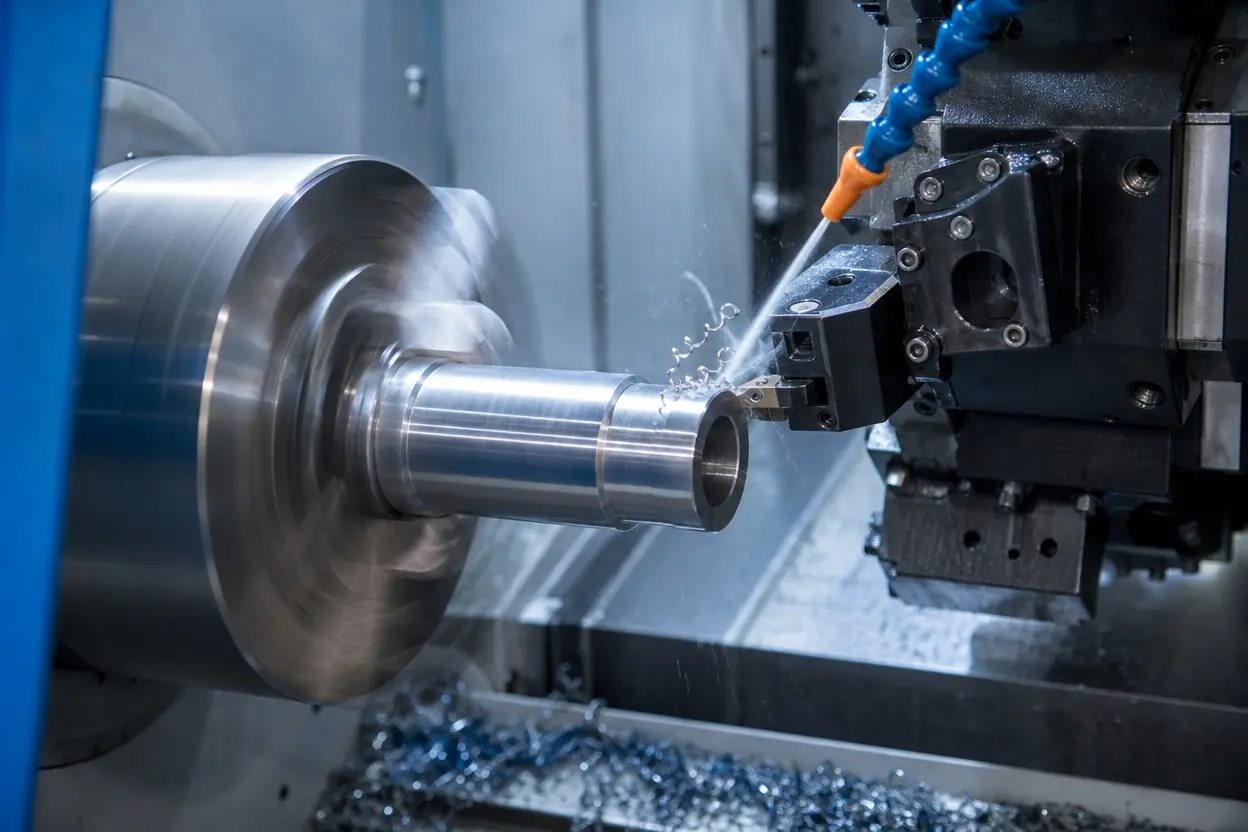
A machining surface finish chart maps each cutting process to the surface roughness, or Ra value, it can realistically hold. Standard CNC turning and milling land between 1.6 and 6.3 micrometers (63 to 250 microinches). Grinding reaches 0.1 to 1.6 micrometers, and lapping goes as fine as 0.025 micrometers (1 microinch).
This guide is built for choosing a process, not for converting units. You get a capability table that names the physical limit behind each number, a turning versus milling comparison, how material changes the result, a feature by feature selection matrix, what each step finer actually costs, what a process holds over a production run rather than on a first article, and a troubleshooting section for parts that come back rougher than specified. If you need to convert between Ra, RMS, Rz, and N grades, or you need the drawing symbols, use our surface finish conversion chart and symbol reference instead.
One note on sources. The roughness parameters here follow ASME B46.1, ISO 21920-2, which defines Ra and the rest of the profile parameter set, and ISO 21920-1, which governs how a finish requirement is indicated on a drawing. The process ranges come from published machining references and from our own 2026 production data. They are realistic production ranges on standard tooling, not best case laboratory figures, because no standard promises a finish for a given process. A drawing that asks for a finish is asking the shop to prove it on the part, every part.
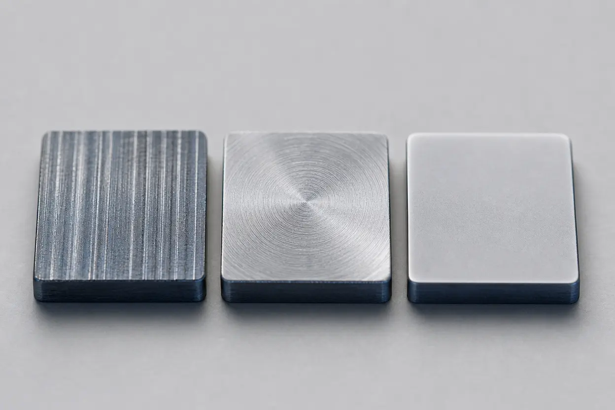
What Surface Finish Can Each Machining Process Achieve?
Machining spans a huge range, from a coarse 12.5 micrometers off a roughing cutter down to 0.012 micrometers off a superfinishing stone. The table below is the quick reference. The last column is the part most charts leave out: what actually stops each process from going finer.
| Process | Typical Ra (µm) | Typical Ra (µin) | Finest practical Ra (µm) | What limits the finish |
|---|---|---|---|---|
| Rough milling | 6.3 to 12.5 | 250 to 500 | 6.3 | Deep cuts and fast feed |
| CNC milling, standard | 1.6 to 6.3 | 63 to 250 | 0.8 | Step-over and the final pass |
| CNC turning, standard | 1.6 to 6.3 | 63 to 250 | 0.4 | Feed rate and tool nose radius |
| Drilling | 1.6 to 6.3 | 63 to 250 | 1.6 | Chips dragging on the hole wall |
| Boring | 0.8 to 3.2 | 32 to 125 | 0.4 | Bar rigidity and chatter |
| Reaming | 0.4 to 1.6 | 16 to 63 | 0.4 | Reamer wear and alignment |
| Broaching | 0.8 to 3.2 | 32 to 125 | 0.4 | Tooth pitch and chip load per tooth |
| Wire EDM, single pass | 2.0 to 3.5 | 80 to 140 | 2.0 | Spark energy in the cut-off pass |
| Wire EDM, with skim passes | 0.2 to 0.8 | 8 to 32 | 0.15 | Number of skim passes and wire condition |
| Sinker EDM | 0.4 to 3.2 | 16 to 125 | 0.2 | Electrode finish and discharge energy |
| Surface grinding | 0.2 to 1.6 | 8 to 63 | 0.1 | Wheel grit and dress condition |
| Cylindrical grinding | 0.1 to 0.8 | 4 to 32 | 0.05 | Wheel grit, work speed, spark-out time |
| Creep-feed grinding | 0.4 to 1.6 | 16 to 63 | 0.2 | Heavy depth of cut and wheel loading |
| Honing | 0.1 to 0.8 | 4 to 32 | 0.05 | Stone grit and stroke rate |
| Lapping | 0.025 to 0.2 | 1 to 8 | 0.025 | Abrasive size and cycle time |
| Superfinishing | 0.025 to 0.1 | 1 to 4 | 0.012 | Stone grit and oscillation rate |
| Mechanical polishing | 0.05 to 0.4 | 2 to 16 | 0.025 | Incoming finish and operator technique |
| Roller burnishing | 0.1 to 0.4 | 4 to 16 | 0.05 | Incoming finish and material hardness |
| Shot peening | 1.6 to 6.3 | 63 to 250 | Adds roughness | Shot size and Almen intensity |
| Bead blasting | 1.6 to 6.3 | 63 to 250 | Adds roughness | Media size and blast pressure |
Two rows in that table are not finishing operations at all. Shot peening and bead blasting are specified for fatigue life and for appearance, and both leave the surface rougher than they found it. If a drawing calls for peening and a fine Ra on the same face, one of those two requirements is wrong, and it is worth resolving before the part is cut.
Cost is the other half of the decision. The table below gives the relative cost per part against a standard machined face at 3.2 micrometers, which we treat as 1.0 throughout this guide. Note that these are per part figures for the operation itself. The cost of a drawing callout, which also carries setup, inspection and the tightening of everything upstream of the finishing step, is covered in the grade table further down and runs higher.
| Process | Relative cost per part | Typical application |
|---|---|---|
| Rough milling | 0.7 to 0.9 | Stock removal, hidden faces, weld prep |
| CNC milling, standard | 1.0 baseline | Housings, brackets, plates, pockets |
| CNC turning, standard | 1.0 baseline | Shafts, pins, bushings, adapters |
| Drilling | Included in the cycle | Clearance and tapped holes |
| Boring | 1.2 to 1.5 | Large or tight bores, bearing bores |
| Reaming | 1.1 to 1.3 | Press fits, dowel holes, sliding pins |
| Broaching | 1.3 to 2.0, low per part at volume | Keyways, splines, internal profiles |
| Wire EDM | 2.5 to 6.0 | Hardened dies, thin webs, sharp internal corners |
| Sinker EDM | 3.0 to 7.0 | Blind cavities, deep ribs, square corners |
| Surface and cylindrical grinding | 2.0 to 3.5 | Bearing seats, hardened faces, gauge surfaces |
| Creep-feed grinding | 2.5 to 4.0 | Deep forms in superalloys, turbine roots |
| Honing | 2.5 to 4.0 | Cylinder bores, hydraulic components |
| Lapping and superfinishing | 5.0 to 10.0 | Gauge blocks, bearing races, optical mounts |
| Mechanical polishing | 2.0 to 5.0, labour driven | Cosmetic surfaces, mould cavities, medical |
| Roller burnishing | 1.2 to 1.6 | Hydraulic bores, sealing diameters |
| Shot peening | 1.3 to 2.0 | Fatigue critical springs, gears, shafts |
| Bead blasting | 1.1 to 1.4 | Uniform matte cosmetic finish, pre-coating |
Which Process Gives the Smoothest Finish?
Lapping and superfinishing give the smoothest finish, down to 0.025 micrometers and, on the right material with enough cycle time, to 0.012 micrometers. Honing and fine grinding sit just above them near 0.1 micrometers. All three are slow and skill heavy, so they are reserved for gauge blocks, bearing races, and seals that leak at anything rougher.
What Is the Roughest Machining Finish?
Rough milling is the coarsest common machined finish at 6.3 to 12.5 micrometers. The cutter moves fast and takes deep cuts, so it leaves obvious marks. It is also the cheapest metal removal you can buy, which is exactly why it belongs on hidden faces.
Surface Finish by Machining Process
Here is what each cutting process is good at and how far you can push it before the cost curve turns. Abrasive processes and EDM get their own sections below, because both behave differently from a cutting edge removing a chip.
CNC Turning
Turning holds 1.6 to 6.3 micrometers on shafts, pins, and bushings. A larger nose radius paired with a slower feed is the fastest way to improve it, because feed marks are geometric and predictable. A dedicated fine pass reaches 0.4 micrometers. Below that, plan on grinding. See our CNC turning services for round part work.
CNC Milling
Milling covers the same 1.6 to 6.3 micrometer band, but it gets there less evenly. The cutter leaves scallops, so the step-over drives the result more than the feed does. Cut the step-over, raise the RPM, and use a sharp finisher, and 0.8 micrometers is reachable on aluminium and steel.
Drilling and Reaming
A drilled wall runs 1.6 to 6.3 micrometers because chips scrape the bore on their way out. Reaming after drilling brings it to 0.4 to 1.6 micrometers and tightens the hole at the same time. Specify reaming when the hole takes a press fit, a seal, or a sliding pin.
Boring
Boring holds 0.8 to 3.2 micrometers and reaches 0.4 with a fine pass and a rigid bar. What limits it is almost never the insert. It is the overhang. A bar running past four diameters of unsupported length starts to deflect and then to chatter, and chatter shows up in the Ra reading before it shows up in the diameter. Anti-vibration bars, a shorter stickout, or a bushing in the fixture buy back more finish than changing the insert grade.
Broaching
Broaching holds 0.8 to 3.2 micrometers on keyways, splines, and internal forms, and the finishing teeth at the back of the tool can bring that to 0.4. The limiting factor is the chip load designed into the tooth pitch, which is fixed once the broach is ground. You cannot slow the feed to improve a broached finish the way you can on a lathe, because the feed is built into the tool. If the finish is not good enough, the answer is a different broach or a burnishing section on the end of the existing one.
Wire EDM and Sinker EDM Surface Finish
EDM does not cut. It erodes material with a series of electrical discharges, and the finish is a field of overlapping craters rather than a pattern of tool marks. That changes how you specify it and how you get it finer.
Wire EDM
A single pass wire cut, the one that separates the part from the blank, leaves 2.0 to 3.5 micrometers. That is roughly a standard machined finish, and it is all many parts need. Going finer means skim passes: the wire returns along the cut face at lower energy and offset, taking off a few microns each time. The first skim typically brings 2.5 micrometers down to around 1.0, the second to around 0.5, and three or four skims reach 0.2 to 0.4 micrometers. Each skim is close to a full pass of machine time, so a four-skim callout can triple the cost of the cut.
The other thing to specify is the recast layer. Every discharge melts a thin film of material that resolidifies on the surface, typically 5 to 25 micrometers deep after a roughing pass, along with a heat affected zone beneath it. Skim passes thin it. For fatigue loaded or medical parts, the recast layer usually has to be removed entirely by polishing, etching, or a light grind, and that is a separate operation with its own cost. A drawing that calls out a fine EDM finish but says nothing about recast is incomplete.
Sinker EDM
Sinker EDM burns a shape with a formed graphite or copper electrode and holds 0.4 to 3.2 micrometers, reaching about 0.2 with fine finishing settings and a dedicated finishing electrode. Two things set the result. The first is discharge energy, since lower energy means smaller craters and a longer burn. The second is the electrode itself, because the cavity is a mirror of the electrode surface and a coarse graphite grade cannot produce a fine cavity. That is why finishing electrodes are made from fine grain graphite or copper and are often used only for the last few tenths of a millimetre.
Grinding, Honing, and Lapping
Abrasive processes remove material with thousands of tiny cutting edges rather than one or two large ones, which is why they reach finishes no insert can. They are also all secondary operations, with their own setup, fixture, and inspection step.
Grinding
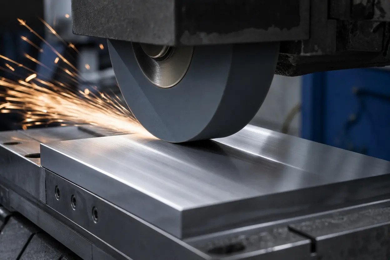
Grinding reaches 0.1 to 1.6 micrometers with an abrasive wheel. It is the default for bearing seats and for hardened parts above roughly 45 HRC, where carbide tooling struggles. Wheel grit and how recently the wheel was dressed matter more than machine speed.
Surface, Cylindrical, and Creep-Feed Grinding
The three common variants are not interchangeable. Surface grinding runs a wheel across a flat face held on a magnetic chuck and holds 0.2 to 1.6 micrometers, reaching 0.1 with a fine wheel and a slow cross feed. It is the usual answer for hardened plates, die shoes, and gauge faces.
Cylindrical grinding turns the part between centres or in a chuck against the wheel and is the finest of the three, at 0.1 to 0.8 micrometers and down to 0.05 on a good machine. Spark-out time, the seconds the wheel spends at zero infeed at the end of the cycle, does most of the final work. Cutting spark-out to save cycle time is one of the most common reasons a ground diameter misses its finish.
Creep-feed grinding takes a single very deep pass at a slow table speed, usually to grind a form straight into solid material such as a turbine blade root. It holds 0.4 to 1.6 micrometers, coarser than the other two, because the wheel is loaded heavily and continuously dressed. It is chosen for form accuracy and for material removal in difficult alloys, not for finish.
Honing
Honing uses abrasive stones to reach 0.1 to 0.8 micrometers and leaves a crosshatch pattern that holds an oil film. That pattern is the point. Cylinder bores and hydraulic components need it to seal and stay lubricated under pressure.
Two details matter when you specify it. The crosshatch angle is set by the ratio of stroke speed to rotation and is typically called out between 30 and 60 degrees included, and plateau honing adds a short fine stage that shears the peaks off the crosshatch so the bore beds in immediately rather than after a wear-in period. Where the function depends on the pattern rather than on the number, say so on the drawing. An Ra value alone does not describe a honed bore, which is why engine and hydraulic prints often add Rk parameters or a bearing area curve alongside it.
Lapping and Superfinishing
Lapping rubs the part against a charged plate to reach 0.025 to 0.2 micrometers. The result is mirror like and slow to produce. It shows up on optical mounts, gauge blocks, and the small number of seals where nothing rougher survives.
Superfinishing is the rotating cousin of lapping. A fine stone oscillates against a turning part, usually a bearing race or a shaft journal, and reaches 0.025 micrometers and below in a cycle measured in seconds rather than minutes. It removes very little stock, typically a few microns, so it corrects finish but not size or form. Whatever geometry error the grinding operation left, superfinishing will leave it too, just shinier.
Turning vs Milling Surface Finish
Both land in the same numeric range, so buyers often treat them as equal. They are not. Turning produces a continuous spiral, which means the roughness is repeatable and easy to predict from feed and nose radius. Milling produces overlapping scallops, so the finish varies with toolpath and part geometry.
| Factor | Turning | Milling | Grinding |
|---|---|---|---|
| Typical Ra (µm) | 1.6 to 6.3 | 1.6 to 6.3 | 0.1 to 1.6 |
| Finest practical Ra (µm) | 0.4 | 0.8 | 0.1 |
| Surface pattern (lay) | Even spiral | Scalloped or crossed | Fine and near uniform |
| Best feature type | Shaft OD, bore, face of a round part | Flat faces, pockets, profiles | Hardened or high load surfaces |
| Getting to 0.8 µm | Slower fine pass, same setup | Small step-over finisher, same setup | Separate operation and setup |
Bottom line: getting a round feature to a fine finish is usually cheaper than getting a flat one there. If a design allows either, we recommend putting the tight callout on the turned feature.
Does Material Change the Achievable Surface Finish?
Yes, and this is where most finish problems start. Two shops running the same program on the same machine will get different Ra values from 6061 aluminium and 316 stainless. The table below reflects typical results across our shops in 2026, using standard production tooling rather than best case lab conditions.
| Material | Typical as-machined Ra (µm) | Finest Ra without grinding (µm) | What gets in the way |
|---|---|---|---|
| Free-machining brass | 0.8 to 1.6 | 0.4 | Very little, chips break cleanly |
| Aluminium 6061 | 1.6 to 3.2 | 0.4 | Gummy at low speed, can smear |
| Cast iron | 1.6 to 3.2 | 0.8 | Graphite pores show in the reading |
| Low-carbon steel 1018 | 1.6 to 3.2 | 0.8 | Built up edge tears the surface |
| Stainless 304 and 316 | 1.6 to 3.2 | 0.8 | Work hardens, needs sharp tools and rigidity |
| Titanium Ti-6Al-4V | 1.6 to 3.2 | 0.8 | Heat and fast tool wear |
| Hardened steel above 45 HRC | Grinding territory | Not practical | Carbide tooling breaks down |
Common Mistake: Copying a Finish Spec Across Materials
A 0.4 micrometer callout that runs fine in brass can force a grinding operation in stainless. We see this most often when a design moves from a prototype material to a production alloy and the drawing notes carry over unchanged. Re-check every tight finish callout whenever the material changes.
Which Process Should You Use for Each Feature?
Process choice is a feature level decision, not a part level one. Use this matrix to route each surface before you finalise the drawing.
| Feature | Target Ra (µm) | Recommended route | Second operation needed? |
|---|---|---|---|
| Hidden flat face | 6.3 to 12.5 | Rough milling only | No |
| Bolted or gasketed face | 3.2 | Standard milling | No |
| Mating or locating face | 1.6 | Milling with a finish pass | No |
| Shaft OD, sliding | 0.8 | Fine turning | Usually no |
| O-ring groove or seal bore | 0.8 | Fine turning or boring | Sometimes |
| Bearing seat | 0.4 | Turn, then grind | Yes |
| Press-fit hole | 0.8 to 1.6 | Drill, then ream | Yes, but same setup |
| Cylinder or hydraulic bore | 0.2 to 0.4 | Bore, then hone | Yes |
| Gauge or optical surface | 0.1 or finer | Grind, then lap | Yes |
What Does Each Step Finer Actually Cost?
Finish is priced in steps, not on a smooth curve. Moving one grade finer inside the same setup is cheap. Moving one grade finer across an operation boundary is not, and the whole skill in specifying finish is knowing where that boundary sits for your material. The multipliers below are relative to a standard machined face at 3.2 micrometers, or 125 microinches, on a mid-volume run, and they hold across our shops in 2026. This table is the reference figure for our surface finish guides, so if you see a different set of multipliers on an older page, use these.
| Target Ra | Cost multiplier vs 3.2 µm | How it is achieved | Extra operation? |
|---|---|---|---|
| 6.3 µm (250 µin) | 0.8 to 0.9x | Roughing pass only, no finish pass at all | No |
| 3.2 µm (125 µin) | 1.0x baseline | Standard turning or milling, no special care | No |
| 1.6 µm (63 µin) | 1.2 to 1.5x | Finish pass, sharp insert, moderate feed | No |
| 0.8 µm (32 µin) | 1.8 to 2.5x | Dedicated fine pass, tighter step-over, tool control | Rarely |
| 0.4 µm (16 µin) | 2.5 to 3.5x | Grinding, honing, or fine turning on the right material | Usually yes |
| 0.2 µm (8 µin) | 4.0 to 6.0x | Fine grinding or honing, plus inspection | Yes |
| 0.1 µm (4 µin) or finer | 6 to 10x | Lapping or superfinishing after grinding | Yes, often two |
The break point sits between 0.8 and 0.4 micrometers for most materials. Everything above it can usually be bought with cycle time on a machine that is already holding the part, so the multiplier climbs in modest steps. Everything below it buys a second setup, a second fixture, and a second inspection point, and from there the figure accelerates rather than creeping up. On stainless, titanium, and anything above 45 HRC the break point moves one grade coarser, to between 1.6 and 0.8 micrometers, because the material will not give you a clean fine pass with a cutting edge.
Why a Grade Costs More Than the Process That Reaches It
Comparing the two tables on this page raises a fair question. The process table prices grinding at 2.0 to 3.5 times a standard machined face and honing at 2.5 to 4.0 times, yet the grade table prices 0.2 micrometers at 4.0 to 6.0 times, and 0.2 micrometers is reached by grinding or honing. Both figures are correct, because they are answering different questions. The process figure prices the grinding or honing cycle on its own, as a line on a route sheet.
The grade figure prices everything a tight callout drags in behind it: the additional setup and fixture, the profilometer verification and the documentation that goes with it, the scrap risk on a part that already has hours of machining value in it, and the fact that the operations feeding the finishing step have to be tightened as well, since a ground face can only be as flat as the milled face underneath it and a honed bore can only be as round as the bored hole it started from. In short, read the process table when you are costing a cycle, and the grade table when you are costing a drawing.
The practical consequence is that 0.8 micrometers is the most cost-effective fine finish in machining. It seals a static O-ring, it carries a sliding fit, and it comes off the same machine in the same setup. If you want to know what a specific number does and does not buy you in service, our guide to what each Ra value means in practice works through the common callouts one at a time.
How to Improve Surface Finish in Machining: The Three Lever Ladder
When a part comes off too rough, the reflex is to add grinding. That is the most expensive answer and usually the third best one. Our engineers climb three rungs in order, and each rung costs more than the one below it.
- Rung one, Tool. Fit a sharp, undamaged insert with the right nose radius and coating for the material. A worn tool is the single most common cause of a rough surface, and swapping it costs minutes.
- Rung two, Path. Slow the finishing feed, lighten the final depth of cut, and shrink the step-over. This adds cycle time on the same machine and the same setup, which is the cheapest real improvement available.
- Rung three, Process. Only when rungs one and two are exhausted, add grinding, honing, or lapping. This means a new operation, a new setup, and often a new fixture.
Pro Tip: Buy the Finishing Pass Before You Buy the Operation
A finishing pass on the machine that is already holding the part adds a small slice of cycle time. A separate grinding operation adds setup, handling, and a second inspection point. We recommend proving out rungs one and two on a sample part before anyone quotes a new operation.
Here is how that plays out. A customer needed 0.4 micrometers on one sealing face of a steel housing and asked us to fine mill the whole part. We milled everything to 3.2 micrometers, then added a short targeted grind on the sealing face alone. The part passed first article inspection on a calibrated profilometer and cost less than fine milling six faces. That kind of routing sits inside our CNC machining and surface finishing services.
First Article Finish Versus Production Finish
Every number in this guide describes what a process holds on a good part with a fresh tool. A production run is a different question, and it is the one that decides whether a program is profitable. Finish drifts across a run, always in the same direction, and the drift is predictable enough to plan around.
The mechanism is tool wear. As flank wear grows on an insert, the effective nose radius changes and the edge stops shearing cleanly, so Ra climbs. On steel and stainless we typically see roughly half a grade of drift across a normal insert life, for example a face that measures 1.4 micrometers on the first article measuring 1.9 to 2.2 micrometers on the last part before the index. On aluminium the drift is smaller until built up edge starts, at which point the finish degrades quickly rather than gradually. On titanium the drift is steep from the beginning, which is why insert life on titanium is often set by finish rather than by breakage.
That leads to three rules we apply when a tight finish goes into production. First, never quote a finish that the first article only just achieves, because there is no wear budget left. If the drawing says 0.8 micrometers, the process has to land near 0.6 on a fresh tool. Second, set the tool change interval on finish rather than on breakage, and write the interval into the control plan so it does not depend on an operator's judgement. Third, measure at the end of tool life, not at the start. A profilometer reading taken on the first part off a fresh insert tells you almost nothing about the parts in the middle of the box.
Roughness is not the only thing that drifts. A ground diameter with a shortened spark-out, a reamer approaching the end of its life, and a wire that has been running at reduced tension all produce parts that measure inside the print early in the run and outside it later. This is exactly what a control plan, in-process sampling, and first article documentation exist to catch, and it is a fair question to ask any supplier before you place a finish-critical order.
Not sure which process your feature needs? Send us the drawing and we will route each surface, flag any finish callout that is costing more than it is buying, and quote against the spec you actually need.
Talk to an EngineerTroubleshooting: The Part Came Back Rougher Than Specified
Most finish failures have a visible fingerprint. Look at the surface under a light before reaching for the profilometer, because the pattern tells you which of the six usual machining causes you are dealing with. The seventh row in the table below is not a machining fault at all, it is the measurement check worth running before anyone touches the part.
| What you see | Likely cause | Fix |
|---|---|---|
| Repeating wavy or fish-scale marks, often with a ringing noise during the cut | Chatter from tool or workpiece vibration | Shorten the tool overhang, add support to the part, change RPM to move off the resonant speed, take a lighter final cut |
| Torn, dull, or flaky surface with material smeared into the marks | Built up edge welding to the cutting edge | Raise cutting speed, use a sharper and more positive geometry, switch to a coated grade, improve coolant concentration |
| Finish good at the start of the run and progressively worse toward the end | Worn insert or reamer | Index the tool, shorten the change interval, set the interval on finish rather than on breakage |
| Rough only on thin walls, long unsupported features, or one side of a pocket | Fixturing deflection or part pushing away from the cutter | Add support or a soft jaw, reduce radial engagement, split into a roughing and a finishing pass with a stress relief between |
| Deep uniform tool marks with clean sharp edges | Feed per tooth too high for the nose radius | Reduce feed on the finish pass or fit a larger nose radius, since Ra rises with the square of feed |
| Burnt colour, heat discolouration, or welded chips in the cut | Coolant not reaching the cutting zone | Redirect or add nozzles, use through-tool coolant, raise pressure, clear chips from deep pockets and bores |
| Readings vary widely across the same face with no visible difference | Measurement problem rather than a machining problem | Confirm cut-off length, direction across the lay, stylus condition, and that both parties are reading Ra and not RMS or Rz |
That last row is worth a second look before anyone scraps a part. A stylus dragged along the lay instead of across it, or a cut-off length set to 0.8 millimetres on one instrument and 2.5 on another, can produce a disagreement of a full grade between customer and supplier on a surface that is perfectly acceptable. If the measurements do not match, reconcile the method before reworking anything. Our conversion chart and symbol reference, linked at the top of this page, covers the parameter and cut-off definitions that cause most of these disputes.
Key Takeaway
Match the process to the feature, not to the part. Route each surface separately, keep tight finishes on the features that seal, slide, or carry load, and let everything else come off at the standard machined finish. Our DFM review flags over specified surfaces on every quote and typically cuts 15 to 25 percent from the machined cost.
For how finish sits alongside tolerance, material, and volume in the total price, read our guide on what it costs to get a metal part made.
Get Every Surface Finished by the Right Process
The wrong process leaves a part too rough to seal. The wrong callout adds a whole operation nobody needed. Meco routes each surface to the right process during DFM review and verifies the result on calibrated profilometers, so you pay for the finish you actually need.
With 30+ years of turnkey manufacturing experience and IATF 16949:2016 certified quality, Meco runs turning, milling, grinding, honing, and EDM under one roof, from prototype through mass production.
- 40+ In-House Processes: CNC turning, milling, drilling, boring, broaching, wire and sinker EDM, grinding, honing, surface finishing, and assembly under one roof.
- IATF 16949:2016 Certified: Automotive-grade quality across every industry, with a 99.99% quality rate and 99.8% on-time delivery.
- DFM Feedback with Every Quote: We route each surface to the right process and flag over-specified finishes, typically saving 15 to 25 percent. Quotes in under 24 hours.
- Profilometer-Verified Finishes: Calibrated Ra measurement at end of tool life, not just on the first article, with full FAI and CoA documentation.
- Prototype to Mass Production: From 10 pieces to 10 million-plus. No minimum order quantities.
Send us your drawings and let Meco's engineering team match every surface to the right process before production starts.
Request a Quote TodayReferences and sources
- ASME. B46.1-2019, Surface Texture (Surface Roughness, Waviness, and Lay). Defines Ra and the parameter set used on North American drawings. asme.org
- ISO. ISO 21920-2:2021, Surface texture: Profile, Part 2: Terms, definitions and surface texture parameters. Defines Ra and the profile parameters. Replaced ISO 4287, withdrawn in 2021. iso.org
- ISO. ISO 21920-1:2021, Surface texture: Profile, Part 1: Indication of surface texture. Governs how a finish requirement is indicated on a drawing. Replaced ISO 1302, withdrawn in 2021. iso.org
Process capability ranges are realistic production figures on standard tooling rather than best case laboratory results, and they vary with machine condition, material and feature access. Cost multipliers are general guidance based on Meco quoting experience, not quotations.
