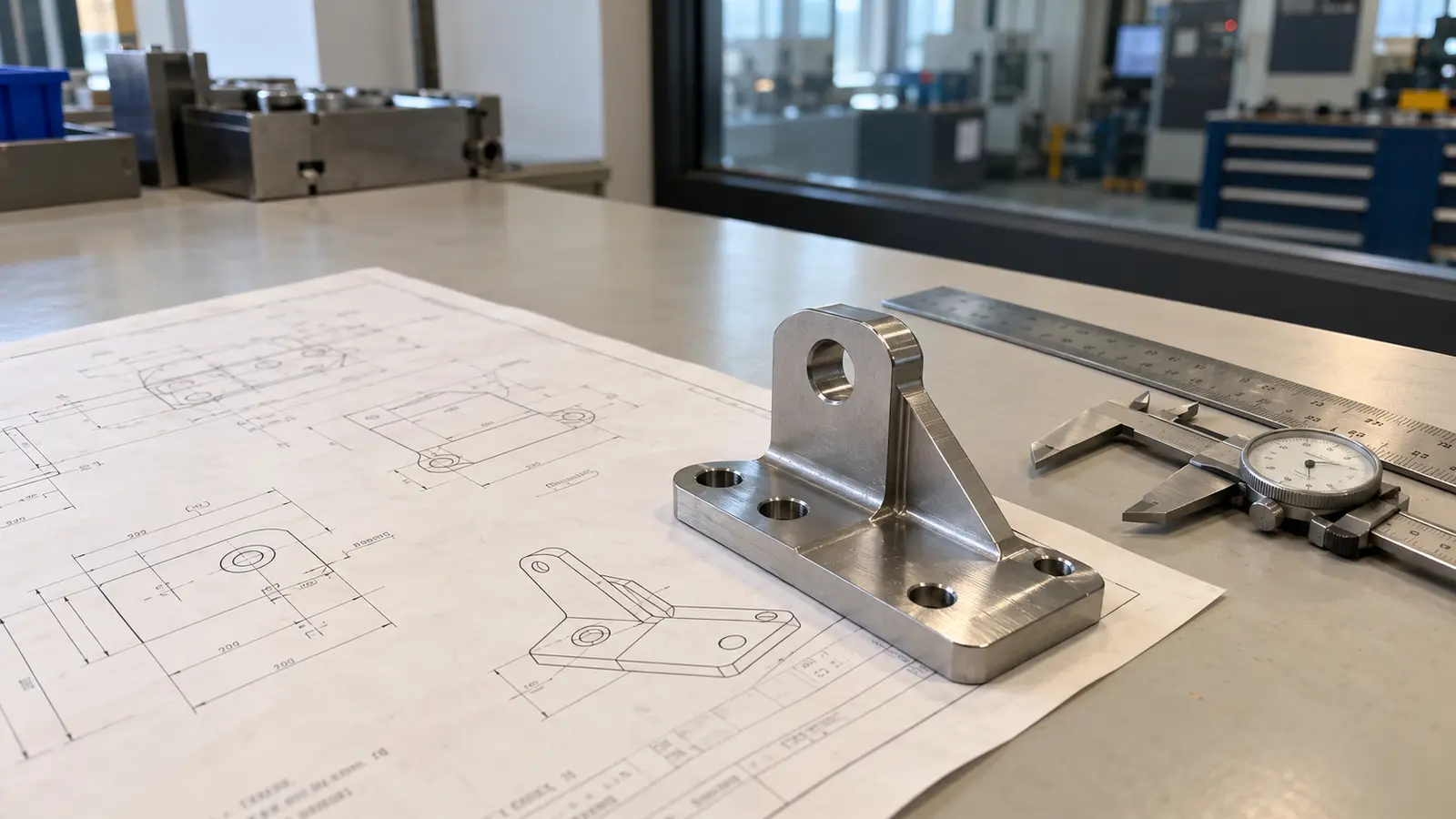
Surface finish symbols on an engineering drawing specify the texture needed on a surface, including roughness limits and whether material removal is required.
A bar on the basic symbol calls for material removal, while a circle prohibits it. Check the Ra or other parameter, the unit, the lay and the standard named on the print.
Surface finish symbols tell a machine shop which surfaces need a controlled texture. They usually sit beside a face or feature on an engineering drawing and combine a small angled mark with limits, units and, when needed, notes about material removal.
The first decision is whether material must be removed, must not be removed, or is left to the chosen process. Then read the roughness parameter, its value and any extra surface requirements.
Those details affect how a part is made, checked and priced. A sealing face may need both a fine Ra limit and a controlled lay, while an unimportant outer surface may not need a special finish.
This guide explains the basic symbol variants, common callout positions and lay marks. It also compares ASME Y14.36 with the newer ISO 21920 rules, so you can read both current and older drawings.
Key takeaways
- Start with the basic mark. The bar calls for material removal; the circle forbids it.
- Read the parameter and unit together. Ra 125 µin and Ra 3.2 µm are nearly the same specification.
- Lay is a separate control. Tool-mark direction can matter for sliding parts and seals.
- Check the standard on the drawing. ASME Y14.36 and ISO 21920-1 govern current practices; ISO 1302 appears on older prints.
- Inspect what the symbol actually asks for. Do not impose an unnecessary process or assume every face needs a polished finish.
What Do Surface Finish Symbols Mean?
Surface finish symbols are drawing marks that state a surface texture requirement. They help a designer tell the manufacturer what result the surface needs, rather than writing a long note beside every feature.
They can define roughness, permitted manufacturing methods, the direction of surface marks and additional measurement details. A symbol applies to the indicated face, not necessarily to the entire part.
The basic checkmark-shaped symbol
The two slanted strokes form the basic surface texture symbol. On its own, it does not demand cutting, grinding or any other specific material-removal step. The intended outcome and the governing standard still control the requirement.
What the machining bar means
A bar added across the basic symbol means material must be removed. Milling, turning, grinding or honing may be suitable, depending on the part and the stated roughness limit. The symbol alone does not choose the machine.
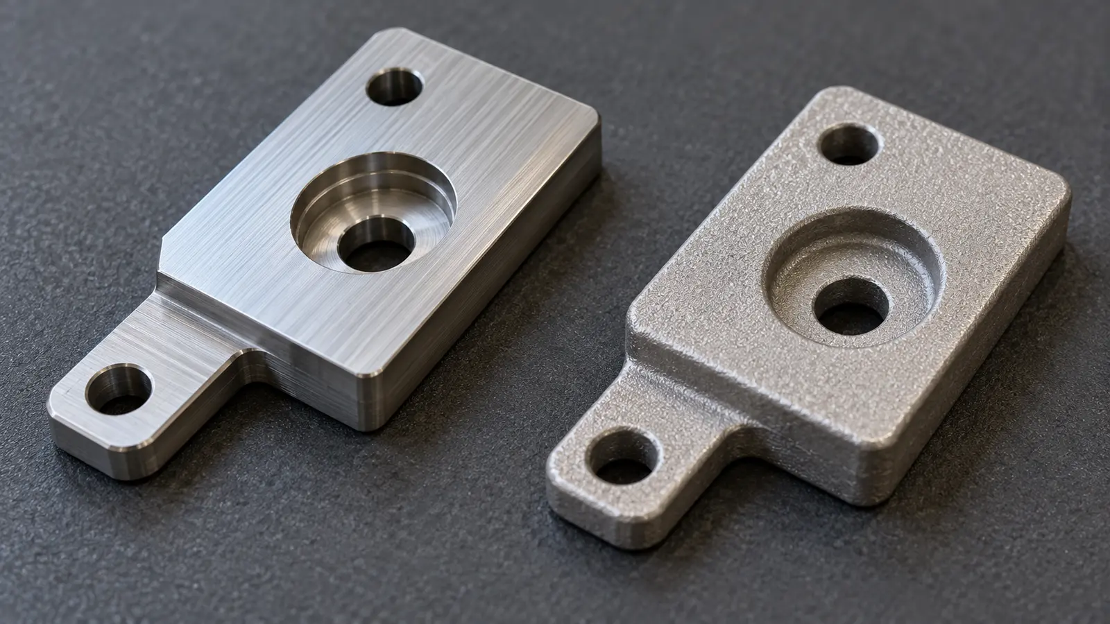
For a cast bracket, a bar on a mounting face tells the shop not to leave that specified surface in its raw cast condition. The exact finish still comes from the numerical requirement and any notes.
What the no-machining circle means
A circle added to the basic symbol means material removal is not allowed. The specified face is usually intended to keep its cast, forged, molded or other as-produced texture.
This avoids adding a finishing pass that the designer did not want. It does not mean the face has no quality requirement or that inspection is unnecessary.
How to Read the Callout Positions
Read a surface finish callout by identifying the base mark, the parameter, the unit and any added notes. The fields around the angled mark carry different instructions, but their precise layout can change with the standard and its edition.
Older diagrams often show lettered positions such as a through f. Use those charts to recognize the types of information, not as a universal layout for every ISO 21920 or ASME drawing.
| Mark or field | What it tells the shop | Example or check |
|---|---|---|
| Basic mark | Surface texture is specified without requiring a particular removal method | Review the drawing notes and referenced standard |
| Bar on basic mark | Material removal is required | Machining or another removal process must be used |
| Circle on basic mark | Material removal is not permitted | Leave the specified face as made by its primary process |
| Roughness field (often a) | Roughness parameter and limit | Ra 3.2 µm or Ra 125 µin |
| Process or treatment field | Required manufacturing method if the drawing specifies one | GRIND or HONE |
| Sampling or evaluation detail | Length or settings used to assess the profile | 0.8 mm where specified |
| Lay field | Direction of the dominant surface pattern | Parallel, perpendicular, circular |
| Machining allowance field | Material reserved for removal | 2 mm, if explicitly shown |
| Additional parameter | Other required surface texture control | Rz, if specified |
The Ra value
Ra is the arithmetic mean deviation of a measured roughness profile. It is a common way to state average roughness, but it does not describe every deep groove or isolated peak.
A lower Ra limit generally asks for a smoother measured profile. On many inch-unit drawings, 125 µin is a familiar value. On metric drawings, 3.2 µm is approximately equivalent because 125 × 0.0254 = 3.175.
See the separate surface finish Ra values guide for typical ranges, and use the surface finish conversion chart to check units.
Method, sampling length and other parameters
A process note such as GRIND or HONE may limit how the result is made. A sampling or evaluation length tells the inspector how to assess the measured profile. Other parameters, such as Rz, can control peaks and valleys that Ra does not describe well.
These are not interchangeable requirements. If the drawing calls for both Ra and Rz, each needs to be interpreted and checked against its own limit.
Machining allowance
A separate allowance tells the shop how much stock is reserved for removal, such as 2 mm when explicitly noted. It does not itself set the final roughness value. The material, geometry and process plan determine how that allowance is used.
What Is Lay Direction in Surface Finish?
Lay is the direction of the main visible or measured pattern on a manufactured surface. Like the grain of wood, it can run along a face, across it, in circles or in several directions.
Lay matters most when two surfaces slide or seal against one another. A shaft that turns under a seal, for example, may behave differently with circumferential marks than with marks running along its axis.
| Lay symbol | Meaning | Typical visible pattern |
|---|---|---|
| = | Parallel to the reference line | Long marks aligned in one direction |
| ⊥ | Perpendicular to the reference line | Marks cross the reference line at right angles |
| X | Crossed in two directions | Intersecting tool marks |
| M | Multidirectional | No single dominant machining direction |
| C | Approximately circular about a center | Concentric circular marks |
| R | Approximately radial about a center | Marks extend outward like spokes |
| P | Particulate or non-directional | Fine scattered texture rather than long lines |
When lay is worth specifying
A bolt-on non-sealing cover usually does not need a special lay symbol. A sliding guide, shaft seal, hydraulic bore or gasket face may. Specify lay because a part needs it, not simply because the symbol is available.
For more information about the surface results of specific machining operations, read the machining surface finish chart.
Surface Finish Standards: ASME vs ISO
ASME Y14.36 and ISO 21920-1 are the current references for surface texture symbols in their respective drawing systems. Older drawings may instead cite ASME Y14.36M or ISO 1302, so the edition printed on the drawing matters.
| Feature | ASME Y14.36 | ISO 21920-1 / older ISO 1302 |
|---|---|---|
| Primary use | U.S. and North American drawing practices | International GPS drawings |
| Current reference | ASME Y14.36-2018 (R2024) | ISO 21920-1:2021 |
| Legacy reference | ASME Y14.36M-1996 may appear on old prints | ISO 1302:2002 is withdrawn |
| Common roughness units | Microinches (µin) on many inch-unit prints | Micrometers (µm) on many metric prints |
| Before making a part | Read the actual cited edition and parameter notation | Use ISO 21920 requirements for new drawings, unless a contract calls for a legacy edition |
What is ASME Y14.36?
ASME Y14.36 sets out methods for showing roughness, waviness and lay controls on engineering drawings. The current designation is ASME Y14.36-2018, reaffirmed in 2024. It does not prescribe which machine must create or which instrument must measure the surface.
Many U.S. and Canadian drawings give Ra in microinches. Still, the drawing's stated units take priority over a regional habit.
What replaced ISO 1302?
ISO 1302:2002 is withdrawn. For graphical indication of profile surface texture, the current replacement is ISO 21920-1:2021. Related parts of the ISO 21920 series address terms, parameters and specification operators.
This matters when an older print is revised. Do not simply copy a legacy field arrangement onto a new drawing and assume all rules stayed identical. Confirm the referenced edition and the inspection specification.
How to Read Any Callout in Four Steps
A fixed reading order reduces the risk of missing a costly detail. Start with what production is allowed to do, then work through the number, direction and extra conditions.
- Check the base. Is it a plain surface texture mark, a bar that requires material removal, or a circle that forbids it?
- Read the number and unit. Find Ra, Rz or another stated parameter. Confirm whether the drawing uses µin or µm.
- Look for lay. Decide whether a direction symbol controls the dominant texture relative to the part.
- Scan all extra notes. Check the named process, evaluation length, stock allowance and any second roughness requirement.
Then check where the symbol points. A callout on one sealing face is not a blanket requirement for every surface of the part.
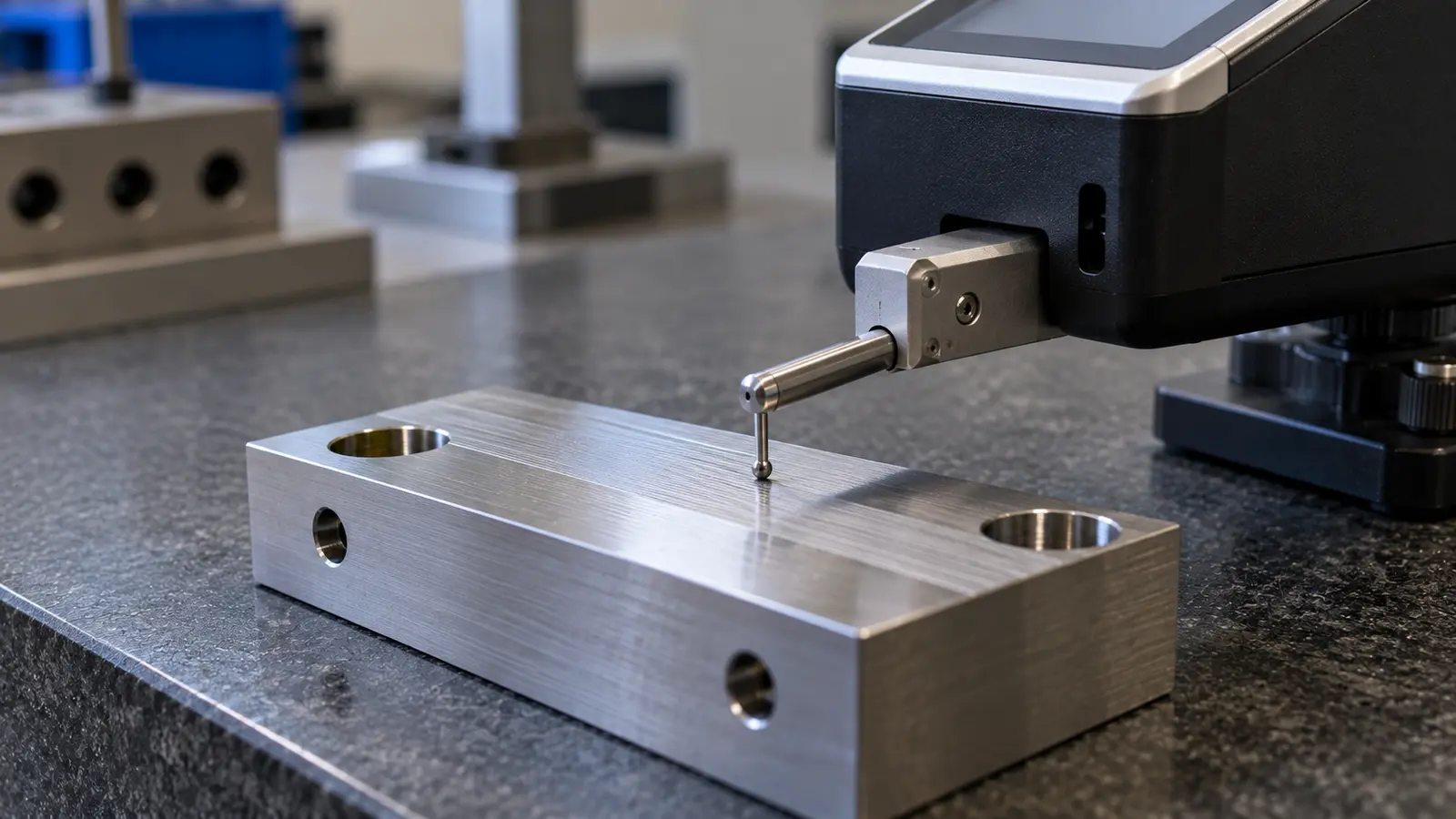
When the finish affects a mating surface, confirm how the measurement will be taken and whether the inspection method follows the referenced standard. A physical comparator can help with a quick visual check, but it does not replace an instrument reading when a numerical limit needs verification.
Not sure about a callout? Send your part drawing, material and target use. Meco can review the texture notes with the machining plan and flag points that need clarification before quoting.
Discuss Your DrawingCommon Surface Finish Symbol Mistakes
The errors with the biggest impact are often a missed bar, a wrong unit or a finish applied to the wrong face. Each can change cost or cause a part to fail fit or sealing checks.
Missing the material-removal bar
Imagine a cast mounting bracket with one face that needs machining for proper contact with another part. If a faint bar is overlooked, that face may be left as cast even though the drawing requires removal. The right response is to review the print and confirm the intended finish before production.
Confusing microinches and micrometers
A limit of 125 µin is about 3.175 µm. A limit of 125 µm is about 39 times larger. Copying the number without the unit can turn a normal machined finish into a very different surface specification.
Assuming every face should be smoother
A lower Ra limit can mean more passes, different tooling or separate finishing. That cost only helps if the part's function needs it. For a surface that only clears another component, extra grinding may add work without improving the design.
Ignoring how the surface is measured
Ra does not capture every scratch, pore or peak. For a functional sealing face, the designer may need an extra texture parameter, a lay note or a more specific inspection approach. Match the measurement method to the print rather than relying only on how shiny the metal looks.
For a broader overview, see the surface finish chart. Meco also provides custom CNC machining and surface finishing services that can be reviewed together when the part needs more than one operation.
Review Your Surface Finish Callouts
A clear callout helps the shop plan the right operation and measure the right feature. Send Meco your drawing and finish requirements for an engineering review.
- DFM review. Material, texture and process feedback.
- Manufacturing options. CNC machining, casting and finishing.
- Inspection planning. First Article Inspection and CMM support where applicable.
- Quality system. IATF 16949:2016 certified.
Explore our surface finishing capabilities before sharing the print.
Request a QuoteReferences and sources
- American Society of Mechanical Engineers (ASME). Y14.36-2018 (R2024), Surface Texture Symbols. Official ASME standard page.
- International Organization for Standardization (ISO). ISO 21920-1:2021, Surface texture: Profile, Part 1: Indication of surface texture. Official ISO standard page.
Read the edition specified on the actual drawing or purchase order before treating an illustrative callout as a manufacturing requirement.
