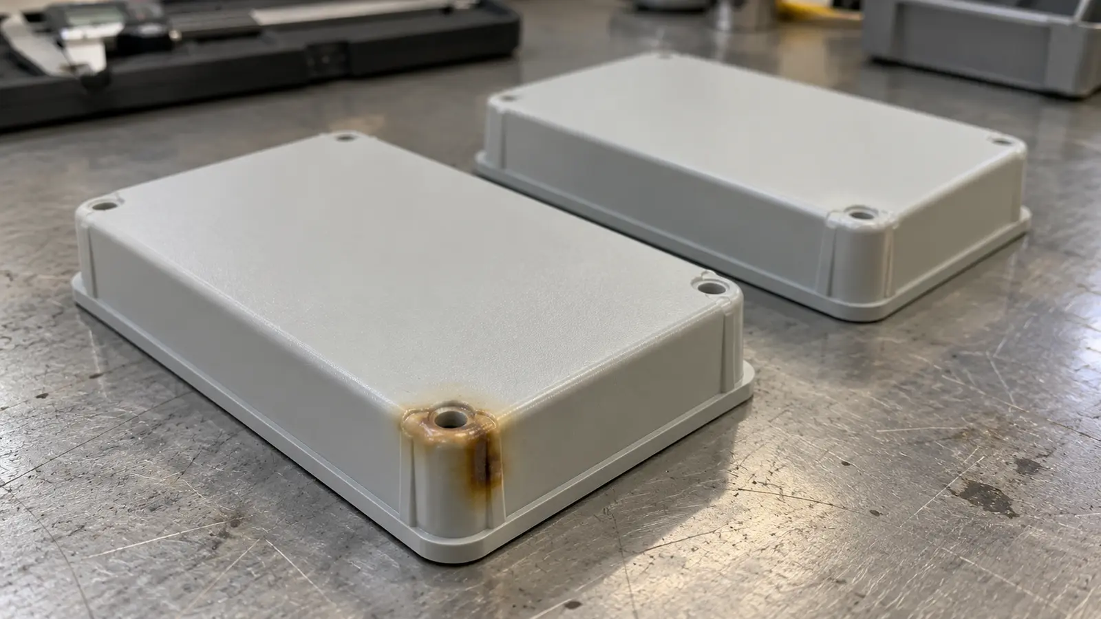
To fix injection molding burn marks, first note where the discoloration appears and whether it repeats. A dark spot at the last area to fill often points to trapped gas and poor venting. Marks that move around, follow a pause in production or appear near the gate may call for a closer check of resin heating and flow.
Start with defect location, vent condition and recent process changes. Then test injection speed, melt condition and the flow path one step at a time. Do not lower every temperature or increase every pressure setting at once.
A molded plastic housing looks good when it leaves the tool. Then a small brown patch appears near a narrow corner. The part is complete, and the dimensions may be correct, yet its surface looks scorched.
One operator may suspect a barrel that is too hot. Another may suspect a blocked vent. Both ideas can be reasonable, but they point to different parts of the process.
Guessing at the cause can waste a trial and even create a new defect.
This article focuses on the marks themselves, not every possible molding problem. Meco's injection molding defects guide gives the broader picture. Here, the aim is to connect the mark's location and timing to the air, heat and material conditions that can produce it.
The most useful evidence often comes from the first few samples: where the mark starts, which cavity made it, how much of the part was filled and what changed since the last accepted run. Those details turn a dark patch into a problem that can be tested.
Key takeaways
- Burn marks are visible signs of local heat damage or degraded material, but a dark mark alone does not prove the cause.
- Trapped air near the end of filling can become hot as the incoming melt compresses it. Poor venting makes this more likely.
- Overheated or long-held resin can also leave dark streaks, especially when the melt experiences strong shear or stays too long in the barrel.
- Match the first check to the pattern. The same mark in the same end-of-fill pocket suggests a different investigation from random marks across many cavities.
- A successful correction must still meet fill, dimensions, surface quality and assembly requirements. A cleaner part that now has a short shot is not a finished fix.
What are burn marks in injection molding?
Burn marks are areas of abnormal darkening on a molded plastic surface. They may look brown, black or lightly charred. A mark may be a small spot at a rib tip, a patch inside a corner or a streak across a more open surface.
A burn is different from an ordinary color change because the plastic may have been damaged by heat. In severe cases, the affected area can be rough, brittle or incomplete. Still, appearance cannot tell you the depth of damage.
A dark part may need comparison with an accepted sample, the material specification and the part's functional requirements.
The place where the discoloration forms matters as much as its color. A mark at the far end of the cavity may be linked to compressed air. A streak near the gate can suggest local shear heating or resin that was already damaged before it entered the mold.
Neither clue is final proof.
Some defects can look similar at first glance. Flow lines in injection molding are usually surface patterns linked to melt movement, not necessarily heat damage. A black speck can also be contamination or aged material.
That difference matters because polishing the surface will not remove a heat source inside the process.
A shallow dent is another different symptom. If the surface has sunk inward over a heavy rib or screw boss, the likely investigation is injection molding sink marks, not a search for trapped gas.
How can trapped air burn the plastic?
When a mold closes, the empty cavity contains air. As molten plastic enters, that air normally leaves through narrow passages called vents. These small openings let gas out while helping keep molten plastic inside the mold.
If the melt reaches a closed corner or two flow fronts meet with no clear gas path, air can become trapped. The moving plastic presses it into a smaller space. The gas heats quickly as it is compressed, and the nearby plastic may discolor or degrade.
This is often called the diesel effect. [1][2]
Imagine a thin plastic cover with a deep rib at one end. The wider wall fills first, while the tip of the rib fills last. If gas cannot escape at that tip, the last push of plastic can heat the gas sharply.
A brown patch may form at the tip even though the barrel temperature stayed unchanged.
Why does the end of fill matter?
The end of fill is the place the molten plastic reaches last. It is not always the point farthest from the gate in a straight line. Flow may split around holes, move quickly through thick areas or slow down in thin regions before meeting again.
That is why a pocket beside an insert or where two flow fronts join can trap gas. Autodesk's air-trap guidance describes both meeting flow fronts and poor vent access as causes of surface damage. [2] The exact location can change with the gate, material, wall thickness and speed.
A short, incomplete feature beside the scorch is a useful clue. Trapped gas can both overheat the local surface and resist the incoming melt. Meco's short-shot troubleshooting guide covers the incomplete-fill side; this article stays focused on why the nearby surface may burn.
Can a burn mark form without trapped air?
Yes. Plastic can also degrade before it reaches the cavity or while it passes through a restrictive flow path. A resin has a safe processing range set by its supplier. Too much heat, time or mechanical work can damage it.
Heat and time inside the barrel
Plastic pellets melt inside a heated barrel. The screw turns to prepare the next shot, and the material waits before it is injected. Residence time means the time the resin spends in this heated system.
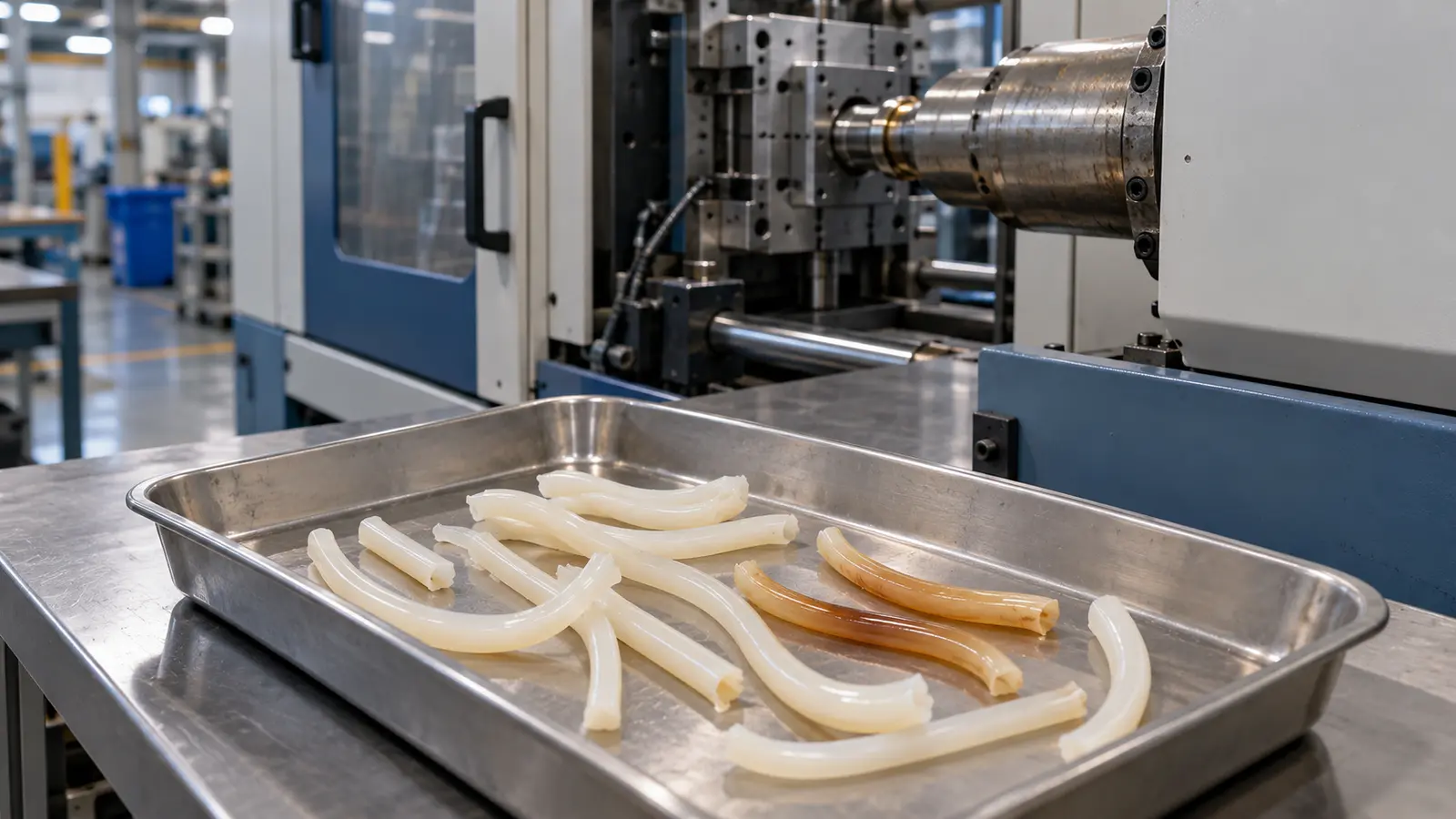
If the material stays hot for too long, some of it may break down. This can happen after a machine pause, during a very long cycle, or when a small part runs in a barrel that holds much more material than each shot uses. The result may be darker streaks, specks or a change in odor. [1][3]
A color or smell change after a pause is useful evidence, but it is not a diagnosis by itself. Check the actual resin grade, how long it was held hot and whether the discoloration clears after the machine returns to stable running.
Extra heat from a narrow flow path
Shear is the sliding force between layers of flowing plastic. When melt is pushed quickly through a narrow gate, nozzle, runner or sharp change in direction, that motion can add heat. The machine display may not show this local rise.
A small gate can therefore contribute to a hot streak even when the general melt temperature is inside the supplier's range. BASF lists high shear, excessive melt temperature and long residence time as separate causes of burning streaks. [3]
The gate is only the opening into the mold. The runner is the channel that carries melt to it. These terms matter because fixing a narrow gate requires a different decision from cleaning a blocked vent at the last point to fill.
What can the mark pattern tell you?
Begin with observation, not a machine adjustment. The table below connects common patterns to sensible first checks. Each row is a clue, not a rule that proves one cause.
| What you see | Possible explanation | First checks |
|---|---|---|
| Same dark patch in one end-of-fill corner | Trapped air or blocked local vent | Part fill pattern; local vent and cavity condition |
| Scorch next to an incompletely filled rib | Gas may resist filling as well as heat the surface | Vent access; rib filling; short-shot samples |
| Burn appears at a flow-front meeting point | Gas trapped where melt streams join | Gate location; flow sequence; vent at the meeting point |
| Dark streaks move from shot to shot | Resin heating, contamination or unstable melt handling | Material lot; barrel and nozzle; purge history |
| Marks become worse after a stop or restart | Long hot residence or stagnant material | Downtime; barrel and hot-runner conditions |
| Marks concentrate near the gate | Local shear heat or already degraded material | Gate and runner geometry; injection profile |
| Only one cavity is affected | A local vent, runner, gate or tool difference | Separate samples by cavity; compare tool condition |
The pattern narrows the search. Confirm the source through controlled checks before changing the tool.
Also separate a real burned area from a surface line where two melt fronts meet. A knit line can form at the same meeting point without any burning. The line itself and a scorched spot beside it call for different inspection decisions.
Location tells you where to begin. Timing tells you what may have changed. A spot that appears only after maintenance should prompt a review of vent cleaning, tool assembly or material handling before anyone changes the approved temperature window.
What causes injection molding burn marks most often?
The causes can be grouped into air removal, melt condition, flow restrictions and part geometry. These groups interact. Fast filling can make poor venting more severe, while a narrow flow channel can add heat to material that was already held too long.
Poor or blocked vents
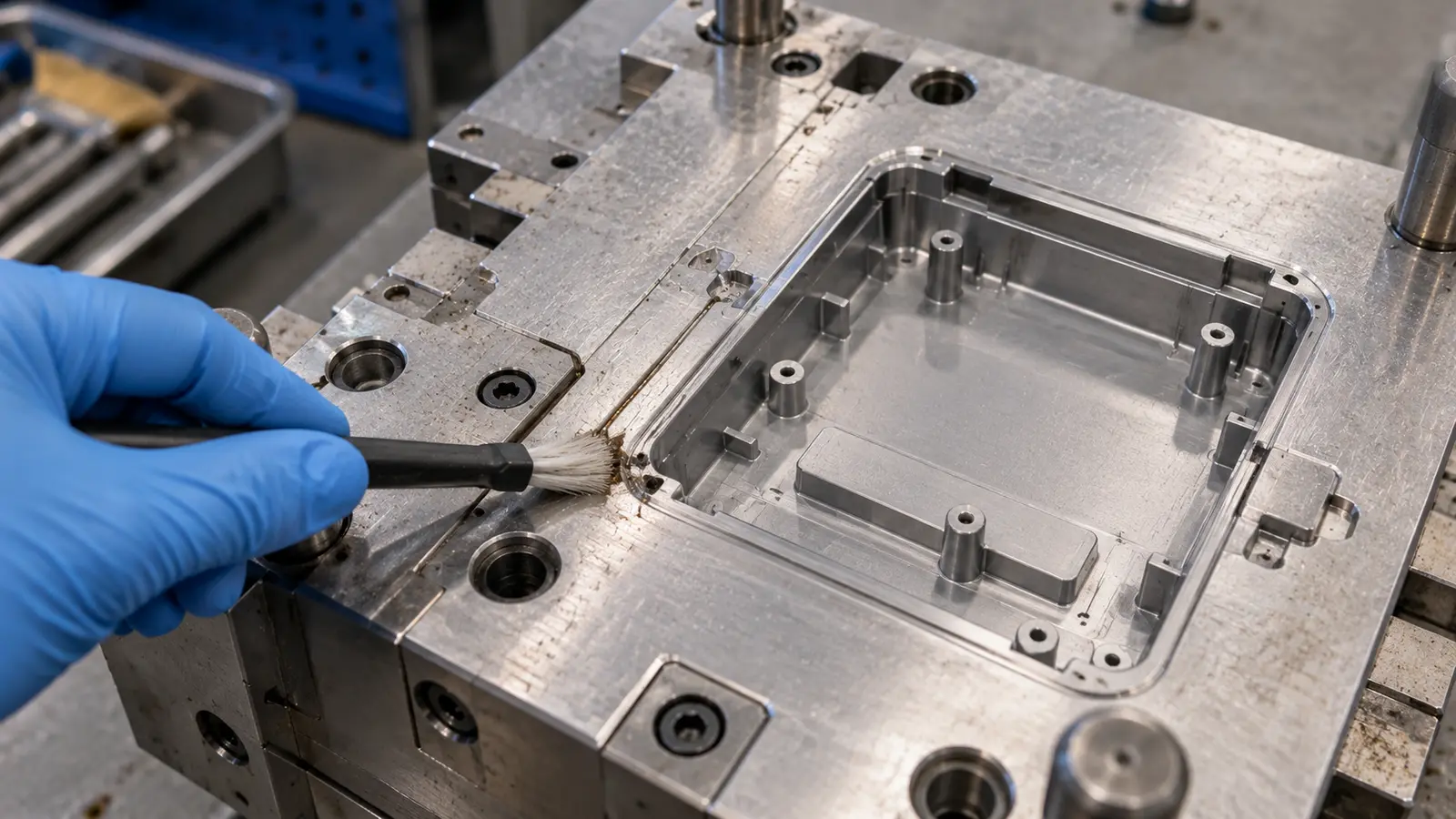
Vents can become less effective when deposits, wear or tool condition reduce the path for gas to escape. If a dark area returns in the same pocket, inspect the vent that serves that region. First check whether the original path is open and clean.
Do not assume that cutting a deeper vent is harmless. Vent size depends on the resin and tool, and an oversized opening can allow flash. Injection molding flash needs a different fix, so toolmakers should review vent changes with both risks in mind.
Many vents use a mold parting surface, where the mold halves close against each other. Meco's parting line guide explains why the condition and location of that joint matter to part appearance and tool performance.
Filling too quickly for the available venting
A high fill speed brings melt into the cavity fast. If gas cannot escape at the same rate, it may become trapped and compressed more sharply. In that case, a slower final stage of filling may reduce burning.
Yet slower filling is not a universal answer. If the flow slows too much, a thin feature may cool and stop filling.
Autodesk notes that speed can sometimes be increased to change a poor flow-front meeting pattern, while a lower speed can help when inadequate venting is the main issue. [2] The correct direction depends on what the fill pattern shows.
Material that is too hot or held too long
An incorrect heater setting, a drifting sensor, high screw work or long residence may take the resin beyond its useful processing window. The actual melt temperature can differ from the number displayed on the barrel controller.
This is why the exact resin grade matters. A material family name such as ABS or nylon does not give the complete drying, melt-temperature or residence limits. Meco's injection molding materials reference offers an overview, but the selected grade's supplier data should control the trial.
Gate, runner and part shape
Sharp turns, small cross-sections and an unbalanced flow path can create both local shear and trapped-air pockets. The same wall may fill differently if a gate moves, even when the material and cycle time stay the same.
A mold with several cavities adds one more question: is the runner sending the melt evenly to each cavity? When only one cavity burns, a local tool problem may be more likely than a change that affects the whole machine.
What should you check before changing settings?
A good first check is simple enough for the team to repeat. Save an accepted part and affected samples where possible. Label the cavity and the point in the run at which the marks appeared.
- Map the mark. Circle its location on a part photo or drawing. Record whether it is at the gate, a rib tip, a corner, a joint between flow fronts or another feature.
- Check repeatability. Compare several shots and each cavity separately. Ask whether the same location is affected every time or whether the mark moves.
- Review the last accepted run. Note any resin, dryer, colorant, regrind, machine, tool cleaning, maintenance or setup changes.
- Check the melt history. Record actual processing conditions, stop time, injection profile and whether the problem appeared after a restart.
- Inspect the gas path. Ask the toolmaker to check accessible vents, deposits and end-of-fill features. Do not change vent depth without a tooling review.
- Compare part function. Record whether the marked area is cosmetic, load-bearing, sealing or part of an assembly interface.
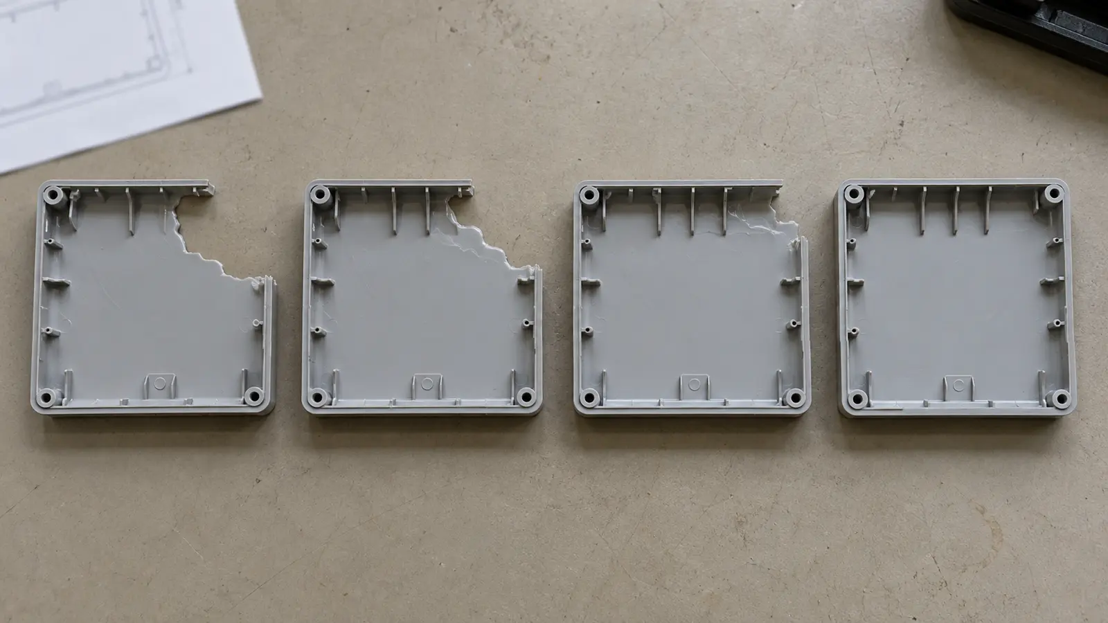
A short-fill study may help show which areas of the cavity fill first and last. It uses controlled, partly filled samples to show the flow path. This work should be planned by the molding team using appropriate process safeguards, not improvised during an unstable run.
A fill study is useful because the visible end of a finished part may not match the real last-to-fill pocket. Once the flow sequence is known, the team can decide whether to investigate the vent, the speed profile or a different gate position.
Which process changes can reduce burn marks?
Process changes are worth testing when the current machine setup is producing extra heat or compressing gas too quickly. They work best when each trial has one stated reason and a clear measure of success.
Adjust injection speed where the mark forms
A machine can use different speeds during the fill. This is called an injection speed profile. A slower last stage may give trapped gas more time to escape at an end-of-fill corner, without slowing the first part of filling as much.
Check the complete molded part after each change. If the scorch disappears but a rib becomes incomplete, the trial has exposed a flow problem rather than solved the full quality requirement. Review the short-shot risk and the vent path together.
Temperature and pressure changes can also affect shrinkage. Meco's warpage troubleshooting article explains why a cleaner surface still needs a check for bending, twisting and assembly fit.
Keep actual melt conditions within the resin limit
Compare barrel and nozzle settings with the resin supplier's instructions, but also check actual melt condition and any hot-runner temperatures that affect the material. Lower a temperature only when the evidence suggests excess heating.
Reducing heat too much can make the melt harder to push through the tool. That can increase pressure demand or prevent thin features from filling. The right target is a stable resin condition, not simply the coldest setting that makes one sample look clean.
Review screw speed, back pressure and residence time
The screw turns to melt and mix material. Back pressure is the force resisting that screw while it recovers for the next shot. Both can change the heat produced in the melt.
If the material shows signs of degradation, compare screw speed, back pressure and residence time against the approved process. Avient and BASF both describe reducing unnecessary heat exposure as a way to address degraded material. [3][4]
After a long stop, follow the resin and machine supplier's safe restart and purge procedures. A purge is the controlled removal of material from the plasticizing system. It can help tell whether dark material was already present before the next part was molded.
Burning in the same location despite stable settings? Share the part drawing, resin grade, mark photos, cavity number and process history. Meco can help review whether the next useful check belongs to the vent, fill profile or tooling.
Burning in the same location? Send the part drawing, resin grade, mark photos, cavity number and process history so Meco can help target the next tooling or process check.
Talk to an EngineerWhen should the mold or part design change?
A tooling review becomes more important when the mark repeats in one pocket under a stable, approved process. If the only clean sample needs extreme settings or develops another defect, the tool may be setting the limit.
Give trapped gas a suitable way out
The toolmaker may need to clean, restore or change vents near the real last-to-fill location. Gas paths can also be made through suitable parting surfaces, inserts or ejector-related features, depending on tool construction. Any change must preserve the shutoff and part requirements. [1][2]
A vent should not be placed just because a dark patch is visible nearby. Confirm the flow path first. A poorly placed vent may not reach the gas pocket that causes the damage.
Review gate position and flow balance
A gate change can move the last-to-fill region to a place with better vent access. It can also change the path around holes, ribs and inserts. That may reduce one gas pocket but create a different join line or appearance issue.
For complex parts, filling simulation can help show where flow fronts meet and where trapped gas may form. Autodesk's burn-mark index is a venting-analysis result for one kind of burn risk, not a test for every source of resin degradation. [5] It should guide a trial, not replace molded-sample proof.
Reduce needless restrictions in the flow path
If burning starts near a small gate or abrupt turn, review whether the runner or gate creates too much shear. A larger or better-positioned cross-section may reduce local heating, but it can also change packing, gate marks and cycle behavior. BASF recommends looking at the full path rather than treating all burning streaks as vent faults. [3]
Mold steel changes need a controlled review, especially on tools already used for production. Where precision metalwork is needed, Meco's custom CNC machining capability is relevant to the broader tooling and component-manufacturing scope. It is not a substitute for the mold designer's vent and gate specifications.
How can burn marks be prevented before production?
Prevention begins before the first accepted production sample. Design, tooling, resin and quality checks need to agree on where the melt flows, where the air leaves and what the finished part must do.
Review end-of-fill pockets during design
In a design for manufacturability review, or DFM, look for blind pockets, deep ribs, thin dead ends and flow fronts that meet in closed spaces. Where possible, avoid a layout that sends the last bit of melt into a hard-to-vent location.
This does not mean removing every deep rib or changing the shape without regard for function. The team must also keep stiffness, strength, sealing and assembly requirements. Meco's R&D engineering services can support this review while gate and mold choices are still open.
Plan the resin and tool together
Select the exact resin grade and confirm its drying and processing guidance. Some materials are sensitive to moisture, but moisture streaks and gas-related burn marks are not the same defect. Drying is useful when the material needs it; it is not a substitute for venting trapped cavity air.
For programs involving tool design, molding and later production under one scope, Meco's turnkey injection molding overview explains how those stages connect. Early agreement on material and gate requirements helps avoid a process window that only works for one trial.
Agree on a clear inspection rule
A cosmetic surface and a load-bearing feature do not have identical risks. Set the allowed appearance standard, the inspection light or viewing conditions when needed, and any functional test that a marked region requires.
For a housing that later fits a metal bracket or gasket, the part should be reviewed as an assembly component. Meco's product assembly services cover that later fit and function stage. A visually clean surface does not prove that every mating feature still works.
How do you verify that the burn-mark fix worked?
One clean sample is a start, not a production release. The result should repeat across the required cavities, resin lots and normal running conditions, using the agreed inspection method.
- Repeat the visual check. Compare the same locations under consistent lighting. Keep marked before-and-after samples and record the sample cavity.
- Confirm complete filling. Check thin ribs, corners and ends of flow. A lower fill speed should not create short shots or new join-line problems.
- Measure the relevant features. Review dimensions, flash, surface quality and any critical seals or fits after the new setup.
- Check stability. Observe samples after the press reaches normal running conditions, and review startup or restart behavior if that triggered the original mark.
- Document the accepted change. Save the approved resin grade, process range, tool revision, inspection notes and reason for the adjustment.
For a new mold, the first article inspection plan can include both appearance and drawing features. For ongoing production, sampling and process records help show whether a fix remains stable rather than working only at one moment.
Meco’s quality management system is IATF 16949:2016 certified, with tools such as first article inspection (FAI), production part approval process (PPAP) and coordinate measuring machine (CMM) inspection where relevant to the project. These methods support traceability and part approval; they do not mean every burn-mark issue can be accepted by measurement alone.
A stable process should also survive reasonable production changes. If a new resin lot, tool cleaning or extended pause brings the mark back, repeat the root-cause check instead of automatically changing the last setting again.
What should a supplier receive for a burn-mark review?
The fastest useful discussion starts with evidence rather than a broad request to remove every defect. A short problem record helps the engineer decide whether the next action is a process trial or a mold review.
- Part drawing and photos showing the burned area from a fixed angle, with an accepted sample if available.
- Exact resin grade, colorant and any material changes, including drying and regrind information if applicable.
- Cavity identification, gate location and what is known about the fill sequence.
- Process history, including injection speed profile, melt conditions, startup timing and the last accepted setup.
- Quality requirement for the marked area, including visible finish, strength, sealing or assembled fit.
Meco's custom injection molding services link design, tooling, molding and inspection in a single manufacturing scope. For readers choosing a supplier for a new program, the injection molding supplier checklist covers wider questions about engineering support, tool ownership and production controls.
Discuss your molded part
Send the drawing, resin grade, defect photos and relevant process history. Meco can help review likely gas-trap, melt-condition and tooling causes before the next test or steel change.
- Design review. End-of-fill pockets, gate position and hard-to-vent features.
- Tool review. Vent access, runner restrictions and mold condition.
- Process review. Fill profile, melt condition and material residence time.
- Quality support. Samples, appearance criteria, fit checks and traceable records.
References and sources
Technical references reviewed 21 October 2026. These sources support air-trap behavior, resin degradation and troubleshooting, not a universal vent size or injection-speed recipe.
- Autodesk Moldflow Insight Help. Troubleshooting burn marks problems.
- Autodesk Fusion Help. Air traps result.
- BASF Performance Materials. Injection-Molding Problems in Engineering Thermoplastics: Causes and Solutions, Burning streaks section.
- Avient. Injection Molding: Troubleshooting.
- Autodesk Moldflow Insight Help. Burn Mark Index Result.
