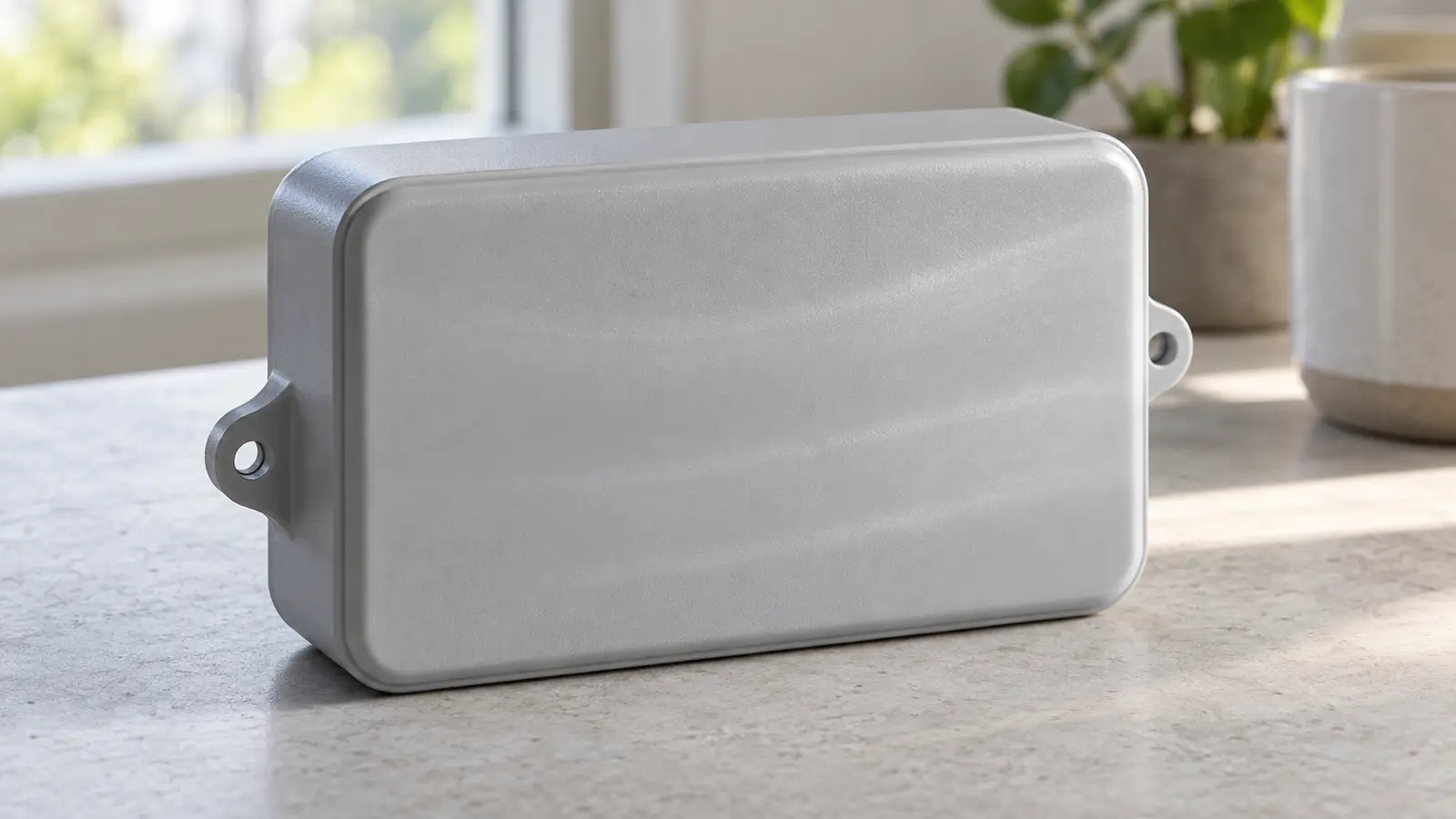
Flow lines are visible waves, streaks or bands on an injection-molded plastic part. They record changes in how the plastic moved and cooled as the mold filled.
To reduce them, first identify the mark, then check the material, filling conditions and flow path.
Key takeaways
- Identify the mark before changing settings. A flow line, a weld line and a scratch can look similar at first.
- Record where it appears and whether it repeats. Those details help narrow the checks, but do not prove the cause.
- Check plastic temperature and mold temperature separately. They describe different parts of the process.
- After a change, check appearance, complete filling and fit. A less visible mark is only part of the result.
A plastic cover can be fully formed and still look uneven. Under a desk light, faint bands may appear across its face. Turn it slightly, and those bands may become easier to see.
That does not tell you the cause yet. The marks could reflect cooling, a change in flow, or the way the material shows light. Similar-looking marks may need different checks.
Our injection molding defects guide explains the wider group of problems. This article focuses on flow lines and what their location can tell you.
Keep a marked sample and a good sample from the same mold, if one is available. Compare them under the same light. Once you can describe the difference, it is easier to choose a useful next step.
What are flow lines in injection molding
Flow lines are the streaks of patterns you find on the surface left by metled plastic when filling a mold. Their appearance may look like rings, streaks or changes in gloss. Even a fully filled plastic part can suffer from flow lines. Judging by their appearance alone cannot tell you if the part works as intended.
The term flow marks is often used for the same problem. Some marks stand out because one area looks shinier or slightly different in color. Others look like fine ripples. They do not have to be deep grooves.
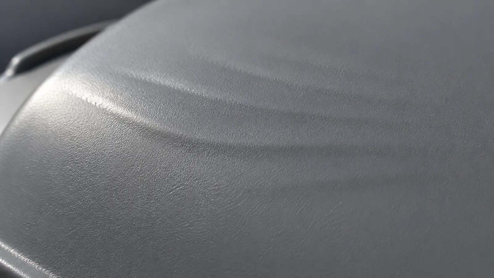
Start by looking at the whole part, then at the marked area. Note whether the pattern spreads from one edge, follows a change in shape, or sits near an opening.
Check whether it is a different kind of line
A weld line, also called a knit line, forms where separate flows of plastic meet. This often happens after the plastic splits around a hole. That joining area can affect strength, depending on the material and use. Covestro explains this distinction in its weld-line guidance. [1]
Jetting leaves a different pattern. A narrow stream enters open space in the mold before spreading against a wall. It may leave a folded, rope-like trail. Treating that mark as a simple cold-flow problem can lead to the wrong speed change.
A parting line marks where sections of the mold meet. A scratch may come from handling or from the part rubbing during release. Silver streaks may involve moisture, gas or damaged material. Ask the molding team to confirm uncertain marks before choosing a fix.
Once you know which mark you are looking at, the next question is how the plastic left it there.
Why does flowing plastic leave a visible mark
A mark can form when the advancing plastic changes speed, cools too soon or meets a sudden change in the flow path. The finished surface can preserve that change. The useful check is what happened at that location while the mold was filling.
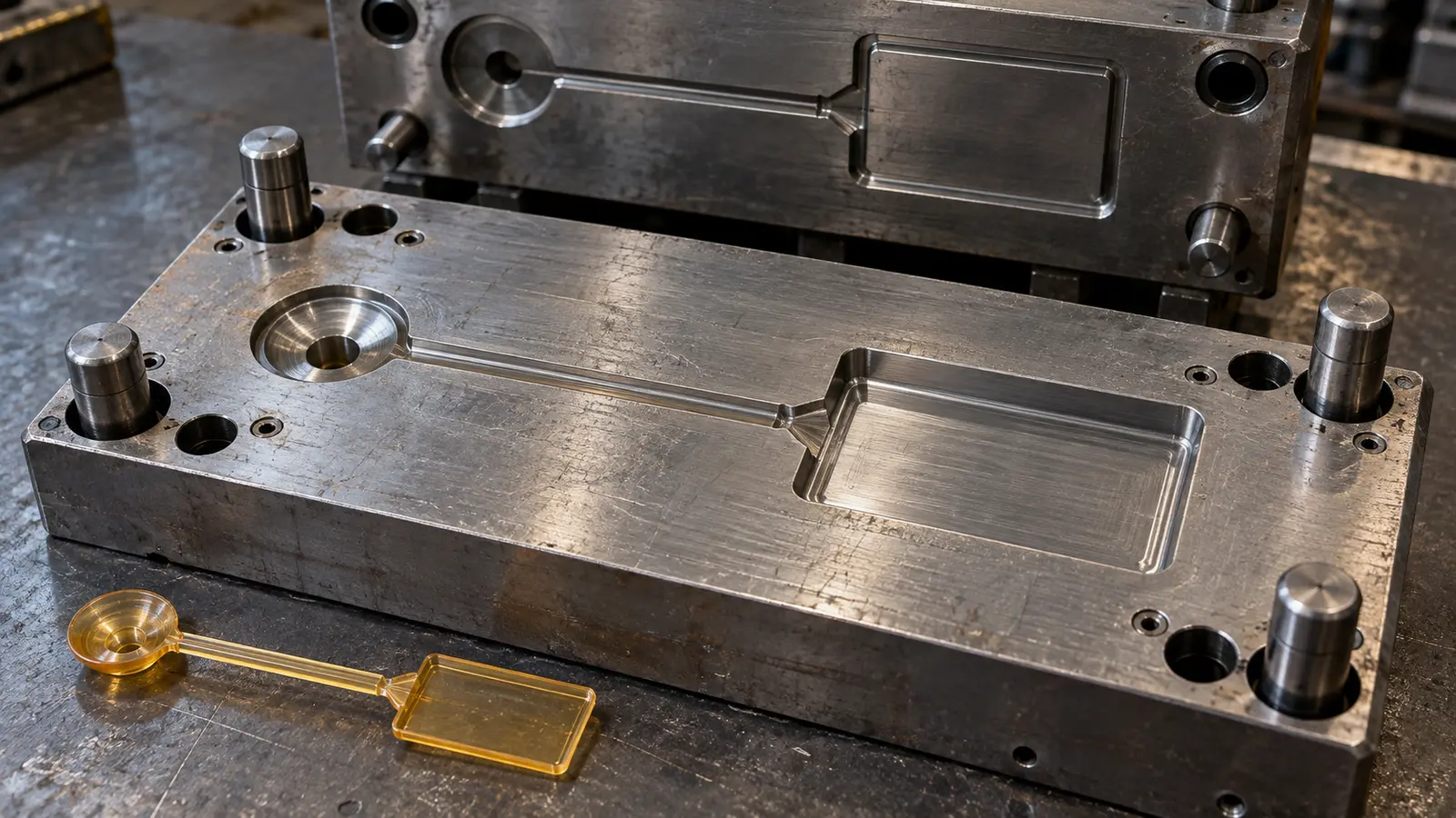
The mold has a shaped space called a cavity. Melted plastic enters it through a small opening called the gate. The leading edge of that moving plastic is the flow front.
As plastic reaches the cooler mold surface, a thin skin begins to form. Warmer plastic keeps moving behind the front. Normally, the plastic spreads and fills the shape before the part cools enough to be removed.
Plastic can cool before the flow has settled
If the material or mold is too cold for the job, the surface can stiffen too soon. Slow filling can give it more time to cool. Later plastic may continue moving while the earlier surface has already started to set.
Autodesk identifies early freezing near the gate and insufficient packing as possible causes of rippled flow marks. [2] That is one reason to review temperature and filling together, rather than assume every visible wave comes from the same setting.
A change in shape can change the flow
Plastic does not move equally easily through every part of the cavity. A thin wall offers more resistance than a thicker route. A sharp turn or a sudden change in wall thickness can also change how the front advances.
If flow slows or briefly stalls in one area, then resumes, it may leave a mark. This delay is called hesitation. For example, plastic may advance along a thicker part of a cover while taking longer to fill a thin side wall.
The material affects how the pattern looks
Resin means the plastic material used for molding. Its exact grade is the supplier's specific product, not just a name such as ABS or nylon. Different grades can flow differently and need different processing conditions.
Colorants and fillers can make changes in flow easier to see. A filler is a material added to the plastic, such as glass fibers. Our injection molding materials guide explains the wider material choices.
These causes leave clues in different places. Look at the position and timing of the mark before deciding which one to investigate.
What can the location of a flow line tell you
The location helps you choose where to start. Compare the mark with the gate, thin sections and changes in shape. Then check whether it appears in the same place on each sample or began after a change to the run.
Where to start your flow mark check
| What you see | What to check first | Why it helps |
|---|---|---|
| Rings or bands near the gate | The mark type, gate area and start of filling | Cold material and disturbed entry flow can require different checks. |
| A mark beside a sudden wall change | Wall thickness and the local filling path | Flow may slow or change direction there. |
| Ripples near the far end of the part | Temperature, filling and the route to that area | The surface may begin to set before filling is complete. |
| Marks on one cavity only | That cavity's gate, temperature and filling | The cause may be local rather than common to the whole mold. |
| Marks after a material or color change | Exact grade, batch, color blend and setup | The new material may behave or appear differently. |
| Marks after a pause or restart | Startup conditions and when the process settles | The first parts may differ from parts made in a steady run. |
These are starting points, not confirmed diagnoses. Similar patterns can have more than one cause.
Take a close photo and a wider photo that shows the mark's position. Record the material grade and any recent change. If there was no earlier good run, use the drawing and agreed sample requirements as the reference.
A part that is missing plastic needs a filling check too. Our short shot injection molding article covers incomplete parts. Flow lines can appear on a complete part, so do not use the terms interchangeably.
With those clues recorded, you can compare the process against the last approved setup.
Which process settings should you check first
Check the material requirements, actual temperatures and filling behavior before making a change. Compare them with the last good run where possible. Ask the process engineer to choose a controlled trial based on the mark, rather than raising every setting together.
Separate plastic temperature from mold temperature
Melt temperature is the temperature of the melted plastic. Mold temperature describes the tool surface around it. Both affect filling, but a change to one does not automatically correct the other.
The heater setting on a screen is a target. It does not by itself prove the actual plastic or local mold temperature. Have the molding team check the relevant temperatures and whether the system holds them steadily.
Stay within the supplier's guidance for the exact grade. More heat may help cold plastic flow, but excessive heat can damage it. A warmer mold can also affect cooling time and part release.
Check how the speed changes during filling
Injection speed describes how quickly the machine delivers plastic during filling. A slow front may cool too early. A fast stream through a narrow gate can create a different surface problem.
The answer may be a speed profile, meaning different speeds during different parts of the filling stage. A controlled start may help plastic spread at the gate, followed by a faster fill where needed.
Eastman's copolyester troubleshooting guide separates flow hesitation from marks linked to high shear. Shear means the deformation that occurs as nearby layers of plastic move at different speeds. Its guidance includes changing the speed profile to suit the cause. [3]
That advice is material-specific. It supports checking the type of mark before choosing a direction, rather than copying a universal speed increase.
Check pressure after the main fill
After most of the cavity is filled, the machine applies packing and holding pressure. These stages feed more plastic through the gate as the part begins to shrink. Once the gate freezes, more plastic cannot pass through it.
Too little packing can leave the surface poorly formed in some cases. More holding pressure will not erase every mark created earlier in filling. Review the stage where the problem begins.
Higher pressure can also create excess plastic called flash. Our injection molding flash article explains why that extra edge may affect fit.
Common mistake: Changing speed, pressure and temperature together leaves you unsure which change helped. During a controlled trial, record each change and keep its sample. Check for new defects as well as a weaker flow mark.
If useful process changes still leave the same mark, review the route the plastic must take through the tool.
Flow lines keep returning? Send part photos, the plastic grade and a note of recent changes. An engineer will review them and help you choose the next check.
Talk to an EngineerWhen should you review the gate or part shape
Review the gate and part shape when a mark repeats at the same feature or improves only at settings that create other problems. The flow path may be making that area difficult to fill cleanly. Settings and design need to work together.
Look at the entrance and the route beyond it
A runner is a channel that carries plastic toward the gate. Check whether the runner and gate suit the material and part. A restriction can change the flow and limit how easily plastic reaches the cavity.
The entry direction matters too. Plastic aimed into open space may behave differently from plastic that spreads against a wall. A larger gate or a new location changes the flow, but can also change the visible gate mark and where flows join.
Cold material at the front of the shot may need attention. A cold slug well is a pocket designed to catch that material before it enters the part. The toolmaker can check whether the delivery system handles it properly.
Look at walls and internal features
Wall thickness means the distance between the inside and outside surfaces of the plastic. More even thickness and gradual transitions can help flow. Changes still need to preserve the part's strength and use.
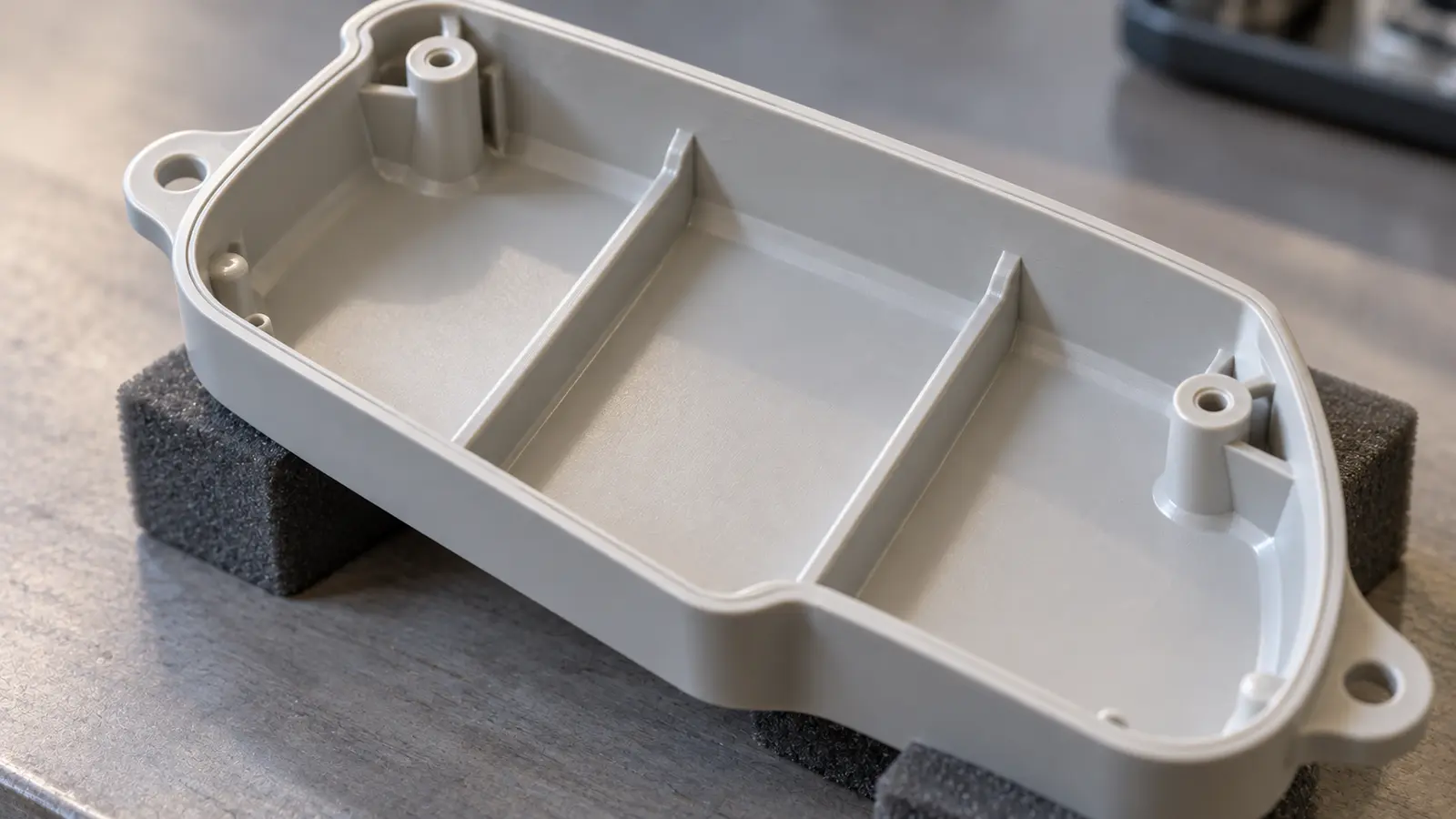
A rib is a thin reinforcing wall. A boss is usually a raised feature around a fixing hole. Their size and position can affect how plastic moves through the cover. Review them with the outer wall, rather than changing each feature on its own.
Imagine a cover with a thin side wall beside a thicker mounting area. If the mark repeats at that transition, compare the local shape and filling sequence. This is an example of a check, not proof that wall thickness caused the mark.
Check local temperature and trapped air
The mold needs to remove heat while keeping the right surface temperature for filling. A local hot or cold area can behave differently from the rest of the cavity. Check the temperature system as well as the machine setpoint.
Vents are small passages that let air escape as plastic enters. Where trapped air or incomplete filling is suspected, the toolmaker should check them too. Vent changes must suit the resin and avoid creating a path for flash.
Meco's custom injection molding services connect part review, mold work and molding. That lets us consider a visible surface alongside the gate, material and shape that produce it.
Flow lines keep returning? Send part photos, the plastic grade and a note of recent changes. An engineer will review them and help you choose the next check.
Talk to an Engineer
How do you know the change has worked
Compare repeated samples under the same viewing conditions, then check the part's size and function. A less visible line is useful only if the part still meets its requirements. Include every cavity and the agreed checks after startup or a restart.
Keep the appearance check consistent
Use the same light, viewing distance and part angle as the agreed check. A mark can seem to disappear simply because the light moved. Compare the new samples with the accepted reference, not just a phone photo.
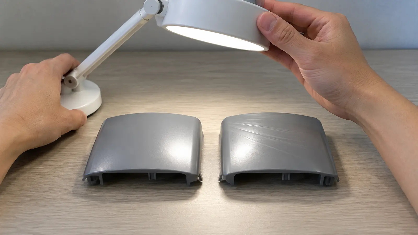
Agree on which surfaces matter most. The front of a visible control cover may need a different finish from a hidden internal support. Record allowed marks by area, so inspectors and suppliers use the same basis.
Check the complete part
- Filling. Check thin walls, corners and clips for missing plastic.
- Dimensions. Measure the features named on the drawing.
- Fit and function. Try the matching parts and the required product checks.
- Other defects. Look for flash, changed color, distortion or damage during release.
- Repeatability. Keep samples and records that show the result can be repeated.
For example, a warmer setup may reduce a visible pattern while changing the cover's size or cooling needs. If the cover no longer seats on its base, the trial has not produced an acceptable result.
Our mechanical assembly guide explains how parts must work together. For a molded cover, appearance and assembly checks should both inform approval.
Acceptance tip: Meco lists a standard molding tolerance of about 0.002 in (0.05 mm). A tolerance is an allowed variation in size. It does not define how visible a flow line may be. Agree on appearance separately, using samples and a clear viewing method.
Save the approved setup with the material grade, mold changes and inspection results. Our plastic injection molding services cover production work where those requirements need to be considered together.
Those records also help when you plan a new mold or a later design change.
What should you agree on before the mold is made
Identify the visible surfaces and agree on how they will be checked before tooling starts. Then review the material, gate and part shape against those needs. This gives the team more options than waiting until a finished mold produces an unwanted pattern.
This work forms part of DFM, or design for manufacturability. It means checking whether the design can be made reliably. For flow lines, ask:
- Which surfaces will the customer see in normal use?
- Where can the gate sit without harming appearance or function?
- Will thin walls or abrupt thickness changes interrupt filling?
- Does the chosen resin and color suit the finish you expect?
- What samples and viewing conditions will define acceptance?
Mold filling analysis is a computer simulation of how plastic may fill the tool. It can help compare gate locations and identify slow or difficult areas. It supports the review, but does not replace molded samples or prove the final surface will be acceptable.
Texture or paint may make some marks less noticeable. If either is planned, review the finished appearance and function after that step. Hiding a pattern does not correct a filling problem or a weak joining area.
We recommend agreeing on a reference sample and viewing method alongside the drawing. A note such as "good surface finish" leaves too much room for different judgments. Clear examples make the required result easier to understand and check.
References and sources
- Covestro, Understanding and optimizing weld lines in thermoplastic molding. Used to distinguish flow marks from joining lines.
- Autodesk Moldflow, Troubleshooting flow marks problems. Used for early freezing and insufficient packing checks.
- Eastman, Injection molding troubleshooting guide for Eastman copolyesters. The draft cites the May 2012 guide, printed page 6. Use current grade-specific guidance for actual settings.
Discuss your molded part
Share the drawing, resin grade and surface photos. An engineer will review the information and advise on the next step.
- Design feedback. Gate, wall and material review.
- Quality support. Dimensions, samples and appearance checks.
- Assembly review. Fit with the matching parts.
Explore custom injection molding services.
Talk to an Engineer