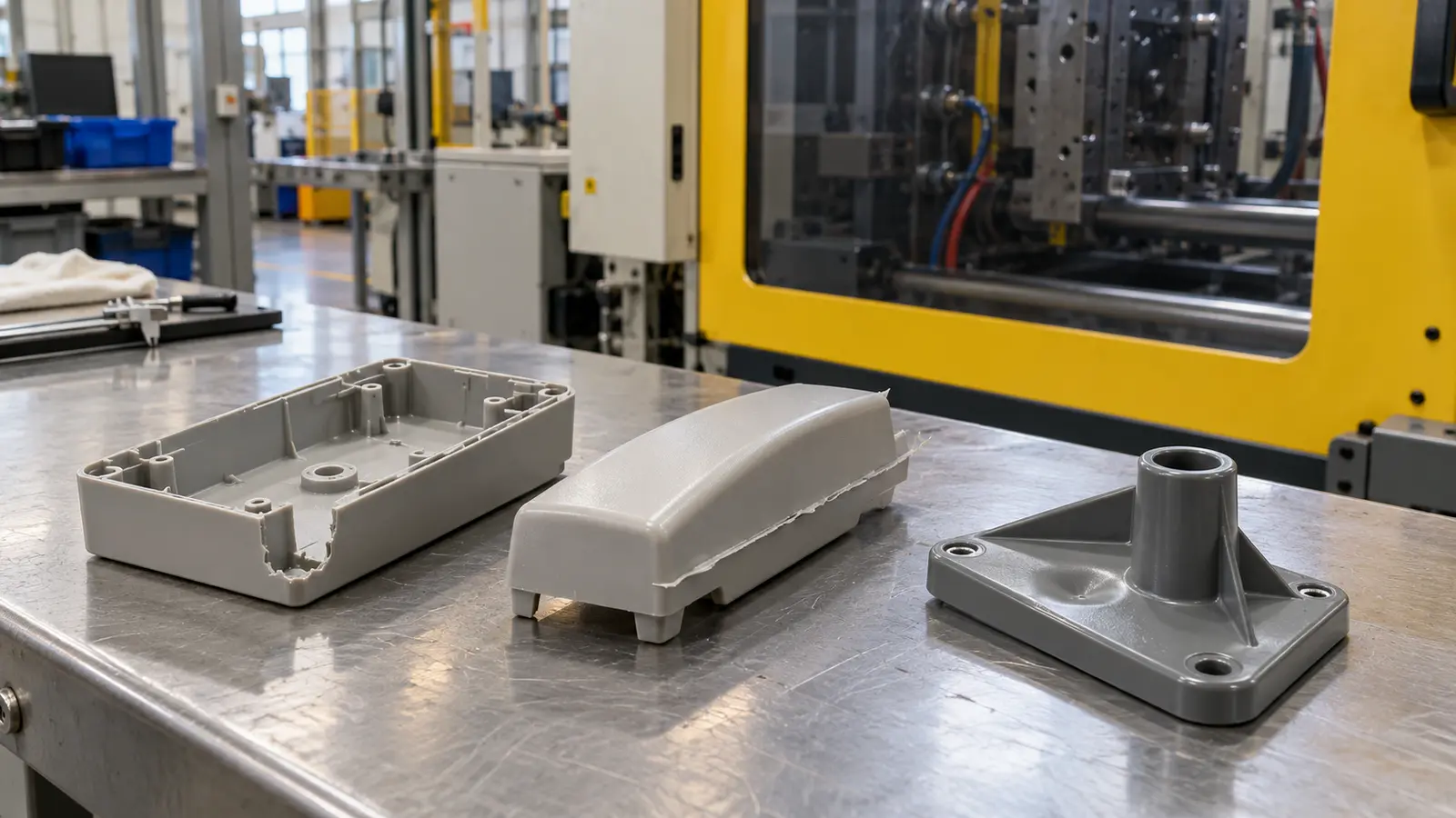
Short shots, flash, sink marks, warpage, burn marks, and knit lines are common plastic defects in injection molding. Their causes may lie in part design, the mold, the material, or process settings.
To narrow it down, look at where the defect appears and whether it shows up in the same place from one part to the next.
Short shots, flash, sink marks, warpage, burn marks, and knit lines are all common injection molding defects. The cause may be related to the part design, the mold, the material, or the process settings.
To narrow it down, look at where the defect appears and whether it shows up in the same place from one part to the next.
- What should you identify before changing process settings?
- Where do injection molding defects usually come from?
- Which defects should you recognize first?
- How do you tell a process problem from a tooling or design problem?
- How can defect risk be reduced before production?
- What should a repeatable troubleshooting process look like?
- When should DFM, tooling, and quality teams be involved?
- Frequently asked questions
- Defects are symptoms. The visible mark does not always reveal the root cause.
- Start with the defect pattern and location before changing pressure, temperature, or speed.
- Separate possible causes into part design, mold and tooling, material, and process conditions.
- Repeated defects in the same location often deserve a design or tooling review, not only a machine adjustment.
- DFM, mold review, sampling, process validation, and inspection can remove risk before production volume increases.
You open the mold, inspect the first parts, and something is wrong. One cavity is not fully filled. Another part has a thin edge of flash. A visible line appears across the surface, and it is not obvious whether the source is the machine, the mold, the resin, or the part design.
That uncertainty is why injection molding defects are better treated as a troubleshooting problem than a list of isolated flaws. A defect is the result you can see. The useful question is what combination of conditions allowed it to appear.
If you are new to the process itself, start with Meco’s introduction to plastic injection molding or the custom injection molding overview. The guide below focuses on diagnosing molded-part defects and reducing the chance that they return.
Key takeaways
- Defects are symptoms. The visible mark does not always reveal the root cause.
- Start with the defect pattern and location before changing pressure, temperature, or speed.
- Separate possible causes into part design, mold and tooling, material, and process conditions.
- Repeated defects in the same location often deserve a design or tooling review, not only a machine adjustment.
- DFM, mold review, sampling, process validation, and inspection can remove risk before production volume increases.
Phase 1: What should you identify before changing process settings?
Before changing any settings, check the defect itself. Similar problems do not always have the same cause.
Look at where the defect appears and whether it shows up in the same place each time. Areas around the gate, parting line, ribs, bosses, inserts, and thin sections can give useful clues. If the problem keeps coming back in one spot, it is usually easier to trace.
Classify the problem before you classify the cause
A practical first step is to decide whether the defect is mainly cosmetic, dimensional, or functional. This keeps the investigation tied to what the part actually needs to do.
- Appearance defects include flow lines, burn marks, visible parting lines, gloss variation, or other surface changes.
- Dimensional defects include warpage, mismatch, shrinkage, or movement of a feature outside its intended tolerance.
- Functional defects include incomplete filling, weak knit lines, poor sealing, or defects in a load-bearing or assembly area.
Not every visible mark has the same consequence. A flow line on a hidden surface may be acceptable for one product. A knit line across a stressed mounting point may require a much deeper review. The acceptance standard should follow the part function, not only the appearance of the sample.
Phase 2: Where do injection molding defects usually come from?
Most plastic defects in injection molding can be traced to one or more of four areas. Looking at these areas separately helps prevent a common mistake: treating every problem as a process-setting problem.
1. Part design
Part geometry controls how molten plastic flows, packs, cools, and shrinks. Large wall-thickness changes, heavy bosses, deep ribs, sharp transitions, long flow paths, and difficult end-of-fill features can increase the risk of short shots, sink marks, warpage, and visible flow effects.
A model can look correct in CAD and still be difficult to mold consistently. Design for manufacturing, or DFM, should therefore review wall thickness, draft, ribs, bosses, cosmetic surfaces, gate-sensitive areas, and features near the end of the flow path before the tool is finalized.
Meco’s R&D engineering service describes the design and engineering support used before a product reaches stable production.
2. Mold and tooling design
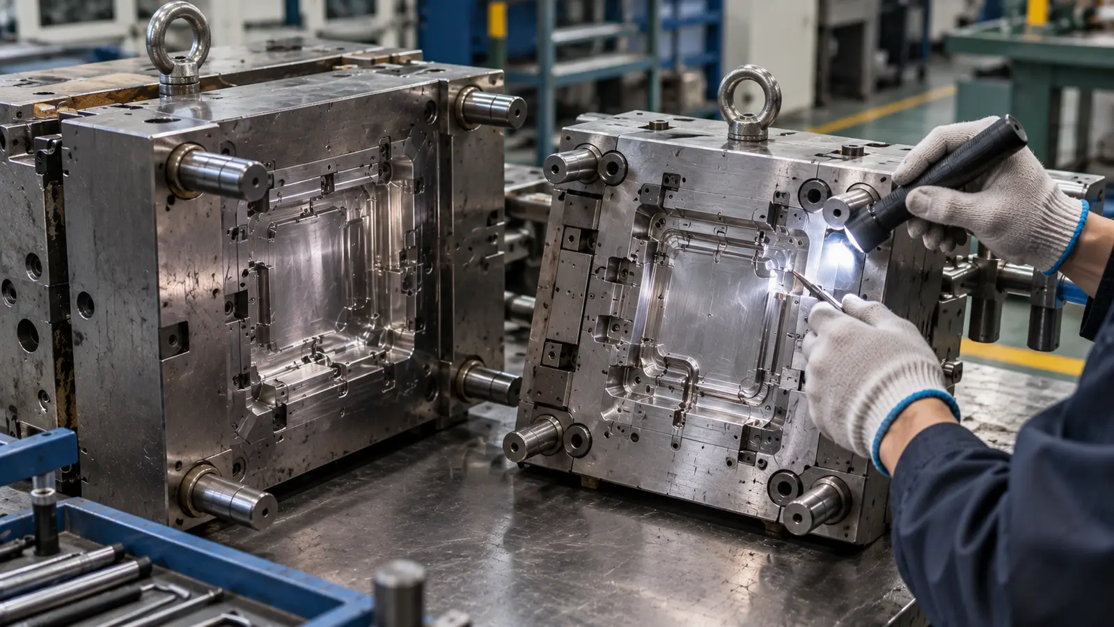
The mold controls how material enters the cavity, where the flow splits and rejoins, how trapped air escapes, how the part cools, and where the mold separates. Gate position, runner layout, venting, cooling, parting surfaces, shutoffs, ejection, and alignment can all change defect risk.
Tool condition also matters after production begins. Wear, contamination, damage, or mismatch at a parting surface can create repeatable defects that do not disappear when pressure or temperature is changed.
3. Material behavior
Different plastics flow, cool, and shrink in different ways. Moisture sensitivity, viscosity, filler content, melt temperature, and shrinkage behavior all affect how a cavity fills. A setting that works for one resin may be unsuitable for another resin, even when the part geometry is unchanged.
4. Process conditions
Injection pressure, speed, melt temperature, mold temperature, holding pressure, and cooling time all shape the final part. These settings matter, but they should be adjusted with a clear reason. If the same defect keeps returning in the same location, the part or tool should also be reviewed.
Phase 3: Which injection molding defects should you recognize first?
| Defect | What you see | Common causes | First areas to check |
|---|---|---|---|
| Short shot | Part is not completely filled | Restricted flow, low pressure, low melt temperature, poor venting, difficult geometry | Gate, runner, venting, pressure, temperature, wall thickness |
| Flash | Thin excess plastic around edges or interfaces | Mold gap, worn tooling, mismatch, high pressure, high melt temperature | Parting surfaces, mold condition, clamp and process settings |
| Flow lines | Wavy or streak-like marks that follow material flow | Uneven flow, cooling, gate location, temperature variation | Flow path, gate, wall transitions, process temperature |
| Knit lines | Line where two flow fronts meet | Flow-front convergence, lower local temperature, gate layout | Gate position, geometry, material and process conditions |
| Parting-line problems | Visible seam, mismatch, or flash | Poor placement, mismatch, wear, weak shutoff condition | Mold design, alignment, parting surfaces |
| Sink marks | Local depressions or dimples | Thick sections, ribs, bosses, packing, uneven cooling | Wall thickness, rib and boss design, packing and cooling |
| Warpage | Twisted or distorted part | Uneven shrinkage, cooling imbalance, material orientation | Geometry, cooling, material, process balance |
| Burn marks | Dark or scorched areas | Trapped air, poor venting, excessive heat or fill speed | Venting, injection speed, melt temperature |
The table below is a first-pass guide. It is useful for narrowing the first area to investigate, but it should not replace root-cause analysis.
What is a short shot in injection molding?
A short shot happens when the plastic does not fully fill the mold cavity. The molded part may look unfinished. Several reasons can account for this, including low injection pressure, low melt temperature, poor venting or even a restricted gate. It is more likely to happen when the section is thin because it may cool down rapidly when the plastic is still flowing into the mold.
A short shot can sometimes be corrected through process changes. If the problem returns in the same area, the gate, venting, wall thickness, and flow path should also be reviewed. If the issue keeps coming back, short shot in injection molding is often worth reviewing from both the process and part-design side, especially filling, venting, temperature, and geometry.
What causes injection molding flash?
Flash is a thin layer of excess plastic that escapes from the intended cavity and forms along a parting line, insert, ejector area, or another mold interface. It may be a small cosmetic issue, or it may show that the mold is not sealing as intended.
Process-related causes can include excessive pressure, high melt temperature, or settings that push material through a small gap. Tooling-related causes can include worn parting surfaces, poor alignment, damage, or an inadequate shutoff condition.
If flash repeatedly appears in the same location, changing machine settings alone may not solve the problem. The mold condition and the local parting surface also need to be checked. Because injection molding flash can come from either the process or the tool, it helps to separate those causes before making further adjustments.
What do flow lines mean in injection molding?
Flow lines are visible streaks, waves, or patterns that follow the path of molten plastic through the cavity. The part may still be completely filled, which is one reason flow lines should not be confused with a short shot.
They can be linked to uneven material flow, temperature differences, gate location, wall-thickness transitions, or cooling conditions. The position and shape of the mark often give useful clues about how the plastic moved through the mold.
For cosmetic parts, gate position and surface expectations should be discussed early. A process change cannot always hide a visible pattern created by geometry or the basic flow path. On visible surfaces, understanding flow lines in injection molding can help show whether the issue starts with gate location, temperature, or the flow path itself.
Do knit lines affect part strength?
Knit lines form where two or more molten plastic flow fronts meet inside the cavity. They are common around holes, inserts, complex features, or areas where the flow splits and rejoins.
A visible knit line does not automatically mean the part will fail. Its importance depends on the line location, material, part geometry, loading direction, and how well the flow fronts bond when they meet.
For a decorative surface, the main concern may be appearance. For a stressed feature, sealing surface, or mounting point, the same line may deserve a deeper design and process review. The location of the line matters as much as its appearance. Knit lines in injection molding need closer review when they cross a stressed area, since their position can matter as much as how visible they are.
Is a parting line an injection molding defect?
A parting line is not automatically a defect. Conventional molds need surfaces where mold components separate, so a line may be visible on the finished part even when the mold is working correctly.
Problems begin when the line is placed on a sensitive cosmetic or functional area, when mold sides do not align well, or when wear and poor shutoff conditions create flash or mismatch. This is why parting-line placement should be reviewed during mold design, not only after the first samples are produced. Injection molding parting lines should be reviewed for placement as well as appearance, especially where mold alignment or shutoff condition can affect the finished part.
What about sink marks, warpage, and burn marks?
Sink marks
Sink marks are local depressions that form when thicker areas cool and shrink differently from nearby surfaces. Heavy ribs, bosses, and uneven wall sections are common places to review. Packing and cooling conditions can also change how visible the mark becomes.
Warpage
Warpage occurs when a molded part bends or twists away from its intended shape. Uneven shrinkage is a common driver. Geometry, cooling balance, material behavior, and flow orientation can all contribute to the final distortion.
Burn marks
Burn marks are dark or scorched areas on the part. They can be linked to trapped air, poor venting, high local temperature, or filling conditions that create too much heat in a small area. Repeated marks in the same location are a reason to review venting and the local flow path.
Phase 4: How do you tell a process problem from a tooling or design problem?
| If you see | First area to review | Other areas to check |
|---|---|---|
| Incomplete filling | Process and flow conditions | Gate, venting, wall thickness, material |
| Repeated flash in one location | Mold condition and parting surface | Pressure, temperature, clamp settings |
| Flow marks | Flow and temperature behavior | Gate location, wall transitions, cooling |
| Weak or sensitive knit line | Flow-front behavior and location | Gate position, geometry, material, temperature |
| Repeated sink marks | Part geometry | Packing, cooling, material shrinkage |
| Warpage | Cooling and shrinkage balance | Geometry, material, flow orientation |
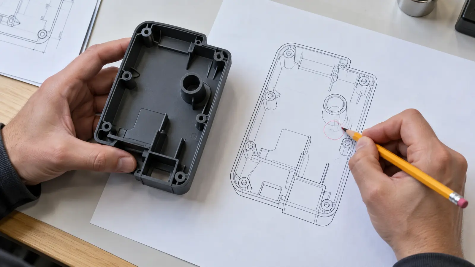
The same visible defect can have more than one possible cause. A useful troubleshooting method starts with the pattern, not with an assumption about the machine.
Common mistake: Changing several machine settings at once can hide the real cause. Define the defect first, identify the most likely cause group, then change one controlled variable at a time when process testing is appropriate.
Phase 5: How can injection molding defects be reduced before production?
Reviewing a recurring defect? Share the part drawing, samples and production requirements so the engineering team can identify questions for design, tooling and process review.
Discuss your partMany defects are easier to reduce before the tool reaches stable production. The goal is not to predict every possible issue. It is to remove avoidable risk before design, tooling, and process decisions become expensive to change.
1. Review the part with DFM
A DFM review should look at wall thickness, ribs, bosses, draft, undercuts, cosmetic surfaces, and difficult flow paths. It should also identify areas where gate placement, ejection, or parting lines may affect the finished part.
This is the stage where a small geometry change can sometimes prevent a much larger troubleshooting problem later.
2. Review the mold as a system
Gate and runner layout, venting, cooling, parting surfaces, shutoffs, ejection, and critical interfaces all influence how the part fills and releases. Reviewing these items together is more useful than treating them as isolated tooling details.
3. Validate the tool with samples
Early molded samples show how the design, mold, material, and process behave together. Visual inspection, dimensional checks, and functional review can reveal whether an issue is cosmetic, dimensional, or likely to affect product performance.
4. Stabilize the production process
Once an acceptable part is produced, the process should be repeatable rather than dependent on one ideal setup. A stable process window reduces cycle-to-cycle variation and makes later troubleshooting more controlled.
5. Inspect what matters to the product
Inspection should match the risks of the part. Cosmetic checks, dimensional inspection, fit checks, and functional tests may all be useful, depending on what the product needs to do. Acceptance criteria should be clear before production volume increases.
For products that combine molded components with other manufactured parts, Meco’s whole product manufacturing service shows how design, production, assembly, and quality can be coordinated under one manufacturing program.
Phase 6: What should a repeatable troubleshooting process look like?
A useful troubleshooting process should be simple enough to use on the production floor and structured enough to avoid random trial and error.
- Define the defect clearly. Describe what is wrong without guessing at the cause.
- Record where it appears. Note the exact location, direction, and relation to the gate, flow path, parting line, rib, boss, insert, or another feature.
- Check whether it is consistent or intermittent. A repeatable problem often points to a different source than a defect that appears only in certain cycles.
- Separate possible causes into part design, mold and tooling, material, and process conditions.
- Change one controlled variable at a time when process testing is appropriate. Multiple simultaneous changes make the result harder to interpret.
- Confirm the correction through repeat molding and inspection. One acceptable sample is not enough if the process cannot repeat the result.
Phase 7: When should DFM, tooling, and quality teams be involved?
The best time to review defect risk is before the same defect has been reproduced across a full production run. Early involvement gives the team more options because geometry, gate strategy, venting, cooling, tooling details, and process approach can still be reviewed together.
Quality should not be treated as a final inspection step only. It starts with the product requirements, continues through DFM and tool design, and becomes visible through sampling, process control, and production inspection.
For a new molded product, the better question is not only, “How do we fix this defect?” It is also, “What created the condition that allowed this defect to appear?” That second question is more likely to produce a correction that lasts.
Meco combines injection molding, engineering support, tooling, finishing, assembly, and broader manufacturing capabilities for programs that need more than a molded component alone.
You can also review Meco's manufacturing capabilities or discuss a part with the engineering team through the contact page.
Discuss your injection molding project
If you are developing a molded plastic part, share the drawing, model, sample, or product requirements before production volume increases. Meco can review the molding scope as part of a broader manufacturing program.
- Scope. Engineering, tooling, molding, finishing and assembly.
- Quality. IATF 16949:2016 certified processes.
Explore Meco’s manufacturing capabilities.
Talk to Meco about your project