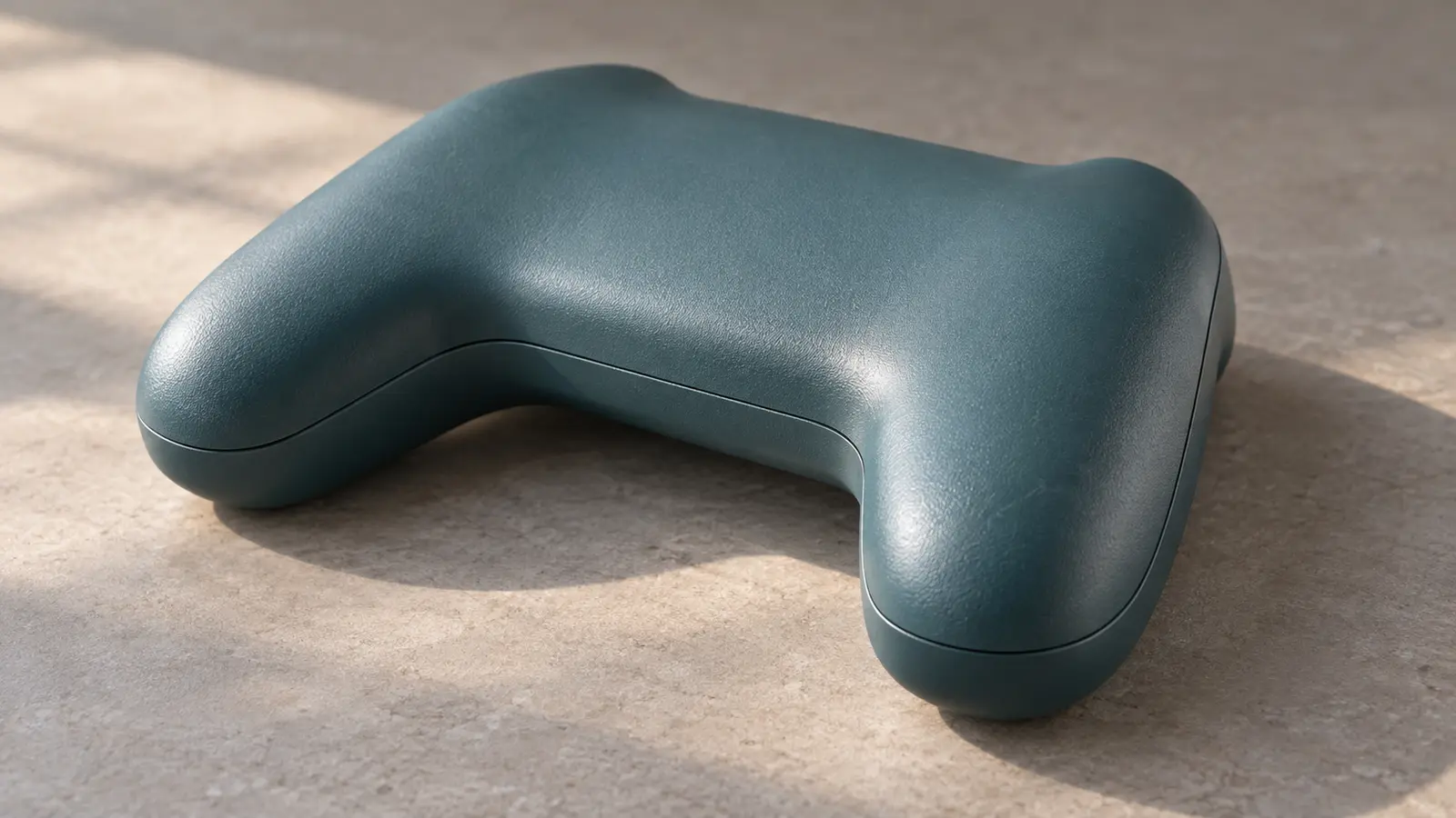
For parting line injection molding, the main design decision is where the mold split travels across the part. The resulting seam is expected, but a raised edge or step near a seal, fit, or show surface may need review.
A molded cover for a handheld controller can look complete and still have a line around its edge. That line alone does not prove that the part is defective. The useful questions are where the mold separates, whether extra plastic or a surface step is present, and what the part must do after molding.
This article focuses on parting-line placement and the marks it can leave. For a wider view of molding problems, see Meco’s injection molding defects guide. It separates this design topic from short shots, flow lines, and flash.
A fine line around a molded housing can be easy to miss until light catches it. On another part, the same line may run across a smooth front face or sit near a seal. The mark needs context before anyone calls it a defect.
The shape of the part, the direction the mold opens, and the surfaces that must fit together all affect where the split can go. This guide explains what the line means, how it differs from other marks, and what to review before the tool is built.
Key takeaways
- What is the parting line? It is the boundary where mold sections meet and open.
- A seam is not automatically a defect. Judge it against the drawing, approved sample, appearance needs, and part function.
- Identify the mark first. Flash is extra plastic, mismatch is a surface step, and flow or knit lines relate to plastic flow.
- Placement creates tradeoffs. Appearance, sealing, fit, release, and tool complexity can all be affected.
- Review the split early. Confirm opening direction, draft, and critical surfaces before the mold is built.
- Check real samples. Use consistent viewing conditions, then confirm the part fits and works as intended.
What is a parting line in injection molding?
A parting line is the boundary left where mold sections meet around the cavity. It follows the planned mold split and opening direction, rather than where two streams of plastic meet.
Start with the mold rather than the mark on the plastic. The tool is divided into shaped sections that meet around the cavity. The edge traced where those sections close determines the seam visible on the molded part.
This boundary comes from the tool layout, not from two streams of plastic meeting. It may appear as a fine witness mark, a small change in surface level, or a faint change in texture.
An injection mold has shaped metal surfaces that form the outside and inside of a part. The hollow space between those surfaces is the cavity. When the mold closes, its two main sections meet along a planned boundary. After the plastic cools, the mold opens along that split so the part can be removed.
The exact boundary depends on the part’s shape and the direction the mold opens. On a simple cup, for example, one side may form the outside wall and the other the inside wall. The mold can separate around the rim. On a box-like housing, the split may run around the sidewall or follow a step in the design.
The split is often called the parting line on the part and the parting surface on the tool. A parting surface is the area where the mold halves or fitted mold sections meet. That contact must support the shape while keeping melted plastic inside the cavity. Autodesk’s parting-surface guidance explains how the surface helps the tool release the finished part.
If the molding process itself is new, Meco’s plain-language guide to how plastic injection molding works explains how the mold fills, cools, and opens.
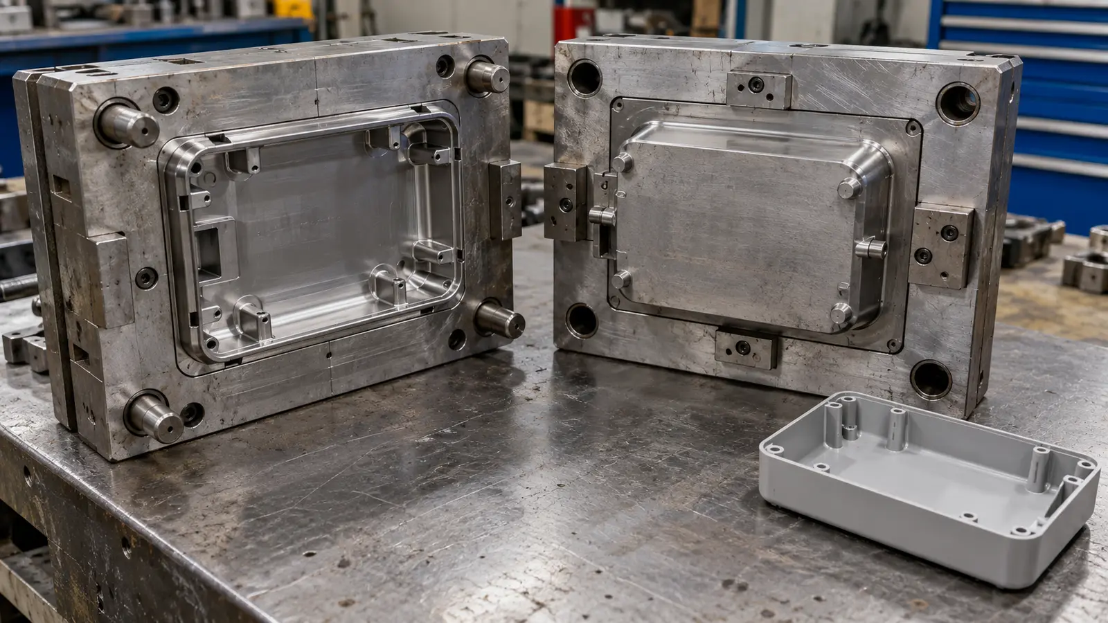
Why does the mold need a parting line?
The mold has to open so the finished part can come out. The parting line marks the route that makes this possible and sets the opening direction that affects part shape and release.
A mold designer chooses which features belong on each mold half. If a wall narrows or widens in the opening direction, the tool may release the part more easily. A small angle on a wall, called draft, gives the plastic room to move away from the steel. A wall with little or no draft may rub, drag, or hold the part during ejection.
Some shapes cannot be formed by two straight-pulling mold halves alone. A side hole, hook, or recessed clip may require a moving tool section called a side action. Side actions add parts and motion to the mold. They can be useful, but the added complexity may affect tool design, cost, and maintenance.
The simplest split is not always the best one. Moving the line to hide it may add a side action or create a difficult shutoff, which is the area where mold surfaces meet to block plastic from entering a space. Design is a tradeoff between appearance, release, function, tooling complexity, and production stability.
How does parting-line placement affect a part?
Parting-line placement can affect appearance, fit, and mold design. Review it against visible surfaces, mating edges, seals, holes, and the direction needed to release the part.
First, consider what a customer sees. A seam on the underside of a housing may be easy to accept. The same seam across a broad, smooth front face may stand out, especially on a glossy surface or dark color. A sharp edge, groove, or natural design break may help the line blend into the part, but it does not guarantee a perfect finish.
Parting-line placement can also affect draft, release, surface marks, and tooling effort. Next, consider what touches or seals against the part. A raised edge near a gasket, snap feature, or mating surface can prevent parts from sitting flat. A line across a precision interface may need a tighter review than one on a non-contact wall. The drawing should identify which faces control sealing, alignment, or assembly.
The line can also affect tool construction. A split that follows a simple outer edge may be easier to build than a path that bends around several undercuts or small features. The more complex path may need extra fitted sections or side actions. That may be justified, but the team should understand the tradeoff before the mold is released for construction.
Meco’s custom injection molding services include design-for-manufacturing review, where the part geometry and tool approach can be discussed before production tooling is committed.
Is a visible parting line a defect?
Not by itself. A narrow, even witness mark can be an expected result of mold construction. Review the part when the line has extra material, a noticeable step, damage, or a position that conflicts with an agreed appearance or functional requirement.
A part owner and molding team should distinguish a normal seam from a defect using the drawing, an approved sample, and the part’s intended use. For example, a faint line on the back of a decorative cover may meet the requirements. A raised edge on a mating rim may stop the cover from closing or sealing.
The word “parting line” describes the location. It does not say whether the surface is acceptable. A visible seam can be acceptable, and a subtle mark can still be important if it crosses a critical sealing or alignment feature.
A short shot in injection molding is different: it means the cavity did not fill completely. Compare it when the part is missing material rather than showing a seam.
A wavy streak that follows the fill path is a different surface issue. Meco’s guide to flow lines in injection molding explains that pattern and its possible causes.
For a deeper explanation of excess plastic at a mold edge, see Meco’s injection molding flash article. The two topics connect, but flash is a condition to diagnose, while this article focuses on where the mold opens and how that boundary should be planned.
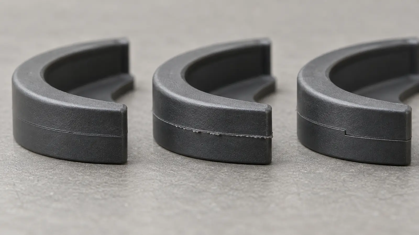
| What you see | Likely description | Why it matters |
|---|---|---|
| Fine seam along a mold split | Parting-line witness mark | May be normal if position and finish meet the agreed requirement. |
| Thin plastic lip beyond the edge | Flash | Extra plastic can affect appearance, fit, or handling. |
| One surface sits higher than the other | Mismatch or step | May point to alignment or tool-fit concerns and can affect assembly. |
| Wavy streak across the surface | Flow line | A surface pattern linked to how plastic moved or cooled. |
| Line where two flow fronts rejoin | Knit line | A separate flow-related mark, not the mold opening boundary. |
What should teams review before the mold is built?
Review the parting line while the design can still change. Compare the mold-opening direction with the part’s appearance, assembly, and release needs before the tool layout is fixed.
Start with a 3D model and ask the mold designer to show the proposed split and opening direction. A line drawn on a flat drawing may not explain how it travels over curved surfaces or around holes. A CAD view, section view, or mold-flow and tooling review can make the path easier to understand.
Then mark the part’s important areas. Identify the show surfaces, gasket lands, mating edges, holes, clips, and dimensions that control fit. If a line crosses one of these areas, decide whether that location is acceptable or whether a different split should be compared.
Check how the part will release. Walls that run parallel to the opening direction may need draft. A feature that traps the part may require a side action, a flexible release, or a design change. The right answer depends on the material, surface texture, geometry, and tool plan.
Finally, agree on how the sample will be judged. “No visible seam” is not precise enough for many parts. State where a witness line is allowed, whether a raised edge is acceptable, and which surfaces must remain smooth or seal correctly. The team can then review actual samples against a shared standard instead of relying on different interpretations.
Meco’s R&D engineering support covers design, prototyping, and engineering review. This is the stage to compare options before tooling decisions become expensive to change.
Why do flash and mismatch appear at the parting line?
Flash is extra plastic that escapes through a gap and cools as a thin lip. Mismatch is a step between surfaces that should line up. They may appear along a parting line, but they have different physical causes.
Flash can be related to the parting surfaces, mold alignment, wear, damage, trapped debris, or process conditions that push plastic into a small gap. A mismatch can relate to how mold sections align or how fitted pieces sit. The visible mark is a clue, not proof of one root cause.
Look at whether the condition repeats in the same place across several parts. Note whether it appeared after tool maintenance, a material change, or a process adjustment. A consistent location may help the team focus its review, but the tool and process should be checked by qualified staff before a correction is chosen.
For causes and checks specific to excess material, use the separate Meco guide to injection molding flash and tooling problems. It explains why lowering pressure without understanding the cause can create a different molding problem.
How can parting-line problems be reduced?
Start with the part design and intended mold split. Place the boundary where a small witness mark is easier to accept, keep it away from critical sealing faces where practical, and confirm the part can release in the planned opening direction.
A visible seam may be easier to manage on a corner, edge, or planned transition than across a smooth panel. The line still needs inspection, but a change in surface direction can make it less noticeable. Avoid assuming that moving the line to the hidden side is free: the new location may need a more complex mold or create a different assembly issue.
Make space for draft on walls that pull from the mold. Draft is not a universal single number. The needed angle changes with wall depth, resin, texture, and tool finish, so the mold designer should confirm it for the part. Increasing draft without checking dimensions can change fit or visible geometry.
Review holes, ribs, clips, and undercuts with the split. These features can affect which mold section forms them and whether a side action is needed. If a small shape change can simplify the split while keeping function, compare that option before adding moving tool components.
Do not treat machining or trimming after molding as the automatic answer. A secondary operation may remove an unwanted edge, but it adds a step and must not damage the part or its fit. First decide whether the line is a normal witness mark, flash, mismatch, or another surface condition. Then compare design, tooling, and process options with the right specialists.
When the molded part is only one piece of a larger product, Meco’s whole-product manufacturing service can connect molding decisions with finishing and assembly requirements in the same program.
Review the split before tooling. Share the part drawing or 3D model with Meco’s engineering team to discuss the planned split, fit, and sealing needs.
Discuss Your ProjectHow should first samples be checked?
Check samples against the drawing and agreed appearance standard, then confirm that the line does not prevent the part from fitting or working. Use the same viewing conditions for every sample.
Inspect the whole part first, then take a close view of the seam. Record the cavity and sample source if the tool makes more than one part at a time. Check whether the line is even, whether material extends beyond the intended shape, and whether one side sits higher than the other.
Next, assemble the part with its matching components. A seam near a cover rim may matter because it affects seating. A line near a latch may affect engagement. A mark on a non-contact surface may be less important, but its acceptability still depends on the agreed requirements.
If a concern remains, share the drawing, the exact material grade, clear photos, and the sample conditions with the molding engineer. The engineer can decide whether to check the tool, review the process, or compare a design change. One appearance observation should not be used to claim a root cause or prove structural performance.
What should be agreed before production?
Before production approval, agree on where the parting line may appear and what condition is acceptable. The drawing or quality plan should identify critical surfaces, allowed witness marks, flash limits if relevant, and the checks needed for fit or sealing.
A parting line is a normal feature of a split mold. Its quality depends on the part’s needs, the surface condition, and the tool’s ability to form the planned shape consistently. Reviewing it early helps the design, tooling, and production teams make the same decision before the mold is committed.
For projects that need molded components, finishing, or final assembly, talk with Meco’s engineering team about the part geometry, material, volume, and acceptance requirements.
Discuss your molded part
Share the part geometry, material, volume, and acceptance needs. Meco’s engineering team can discuss the mold approach and related finishing or assembly needs.
- DFM feedback. Part geometry and tool approach review.
- Process coordination. Molding, finishing, and assembly planning.
- Quality system. IATF 16949:2016 certified.
See Meco’s manufacturing capabilities and custom injection molding services.
Talk to an EngineerReferences and sources
- Autodesk. Parting surface in injection mold design. Autodesk Inventor Help.
