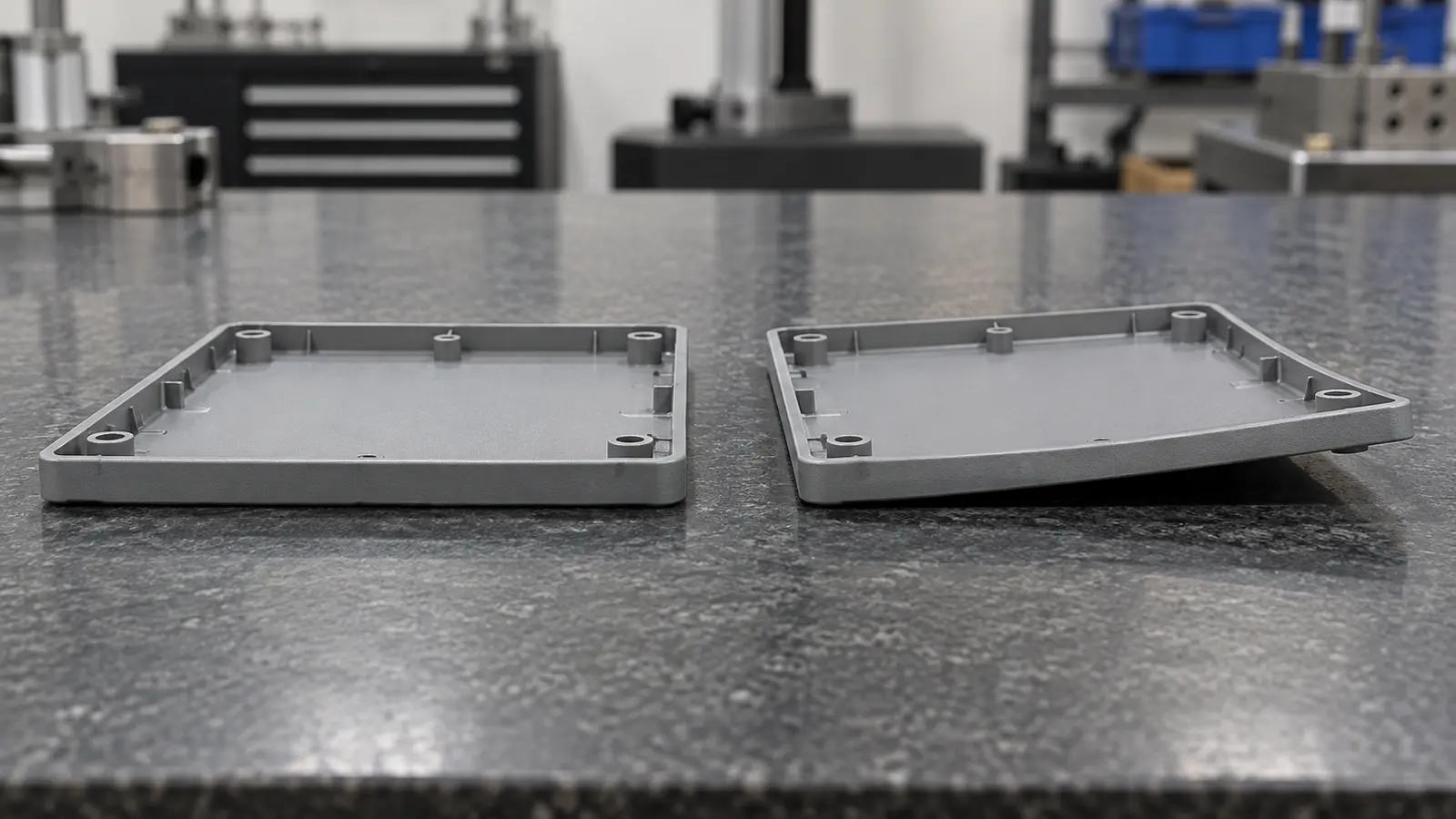
Warpage in injection molding is an unexpected change caused by uneven shrinkage as the molded part cools. To identify this, start by measuring where the part bends or twists, then compare cooling balance, packing, wall thickness, gate position and resin behavior before adjusting settings.
A process trial can help when the cause is uneven temperature or pressure. If the same area keeps moving under stable conditions, the part design, gate, cooling layout or material may need review.
A flat plastic cover comes out of the mold and looks acceptable in the operator's hand. Ten minutes later, one corner lifts from the inspection table. When the cover is fitted to its base, a gap appears along one side.
The problem is not always obvious at ejection. Plastic keeps cooling after it leaves the mold, and stored stress can relax as the part reaches room temperature. A part that looked straight at the press can therefore move later.
Warpage is one of the dimensional defects covered in Meco's injection molding defects guide. This article stays with the shape change itself: why different areas shrink by different amounts, what clues the direction of movement can give you, and how to decide whether the next step belongs in the process, the mold, the material or the part design.
Before changing a machine setting, keep a warped sample and an accepted sample from the same tool where possible. Record the cavity, resin grade, time after molding and the way the part was measured. Warpage is much easier to troubleshoot when every comparison uses the same conditions.
Key takeaways
- Overall shape. Warpage changes the overall shape of a molded part. It may appear as bowing, twisting, corner lift or a panel that no longer sits flat.
- Uneven shrinkage. The basic driver is uneven shrinkage. Different regions, layers or material directions pull against one another as the part cools.
- Connected causes. Cooling, packing, wall thickness, gate position and material orientation can all affect the final shape.
- Controlled changes. A setting change should be controlled and measured. A flatter part is not a successful fix if it creates flash, short shots, size changes or poor assembly fit.
- Repeatable evidence. Review repeatable distortion early. Stable warpage in the same direction can point to geometry, cooling layout, gate strategy or material behavior that process settings alone cannot remove.
What is warpage in injection molding?
Warpage means a molded part no longer holds the shape intended by the drawing after cooling and release. A broad face may bow, a long wall may curve, a corner may lift, or the complete part may twist enough to miss an assembly point.
The key word is shape. Normal molding shrinkage makes a part smaller as the plastic cools. If the part shrinks evenly, its dimensions may change while its overall form stays similar. Warpage begins when shrinkage is not balanced.
A warped part can still look complete. It may have no missing corner, no flash and no obvious surface mark. The problem often becomes clear only when the part is placed on a flat reference, checked in a fixture, measured against datums or assembled with its mating components.
How is warpage different from a sink mark?
A sink mark is a local depression, often over a thick rib, boss or wall section. Warpage changes a wider part of the geometry. A flat lid that becomes curved is warpage; a small dimple over one boss is closer to a sink mark.
Both can involve shrinkage, so they may appear on the same design. The distinction matters because the acceptance check is different. A sink mark may be judged by surface appearance and local dimensions, while warpage often needs flatness, profile, hole position or assembly checks.
Readers who are new to the molding stages can use Meco's explanation of plastic injection molding for the fill, pack, cool and ejection sequence. Those stages matter here because the part's final shape is built up across the whole cycle, not at one single moment.
Why does uneven shrinkage bend a molded part?
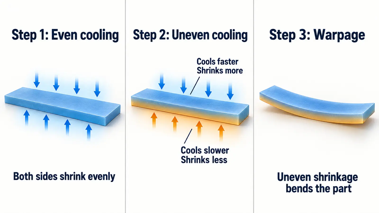
If every area of a molded part contracted by the same amount and in the same direction, the part would mainly become smaller. Warpage appears when one area or direction wants to shrink more than another, creating stress that the free part releases by bending or twisting.
Autodesk describes warpage as the result of shrinkage differences from region to region, through the thickness and along different material orientations. Its Moldflow documentation also separates effects from differential cooling, differential shrinkage and orientation. [1][2]
Different regions can shrink by different amounts
A thick section stays hot longer than a thin section. An area near the gate may also receive more packing pressure than a remote area. If those regions leave the mold with different density and temperature histories, they may contract by different amounts later.
This is why an abrupt wall change can influence more than appearance. One side of a broad cover can pull harder than the other as it cools, and the full panel may curve even though each section was completely filled.
The two faces of a wall can cool differently
Think of a flat panel between the cavity side and core side of the mold. If one mold surface runs warmer than the other, the plastic near each face cools at a different rate. The two sides then develop different shrinkage and stress.
That imbalance acts like two layers that want to become different lengths. Once the steel no longer holds the part, the panel can bow. Autodesk treats this through-thickness temperature difference as a direct contributor to warpage. [1]
Flow and fiber orientation can change the direction of shrinkage
Plastic does not always shrink the same way in every direction. Flow through the gate lines up polymer chains to some degree, and short glass fibers can align strongly with the melt flow.
For fiber-filled materials, shrinkage along the fiber direction can differ from shrinkage across it. A gate change can therefore change more than where the part fills first. It can change the orientation pattern that helps set the final shape. Autodesk recommends considering gate location, wall thickness and molding conditions when orientation is a major warpage driver. [4]
The practical point is simple: two parts made from the same plastic can warp differently if their flow paths, wall shapes or cooling conditions are different. Material name alone is not enough to predict the result.
What can the shape of the warp tell you?
The direction and timing of the movement can help the team decide where to look first. It is a clue, not proof of one root cause.
| What you see | What to check first | Why it helps |
|---|---|---|
| One corner lifts from a flat surface | Core and cavity temperatures, local cooling, corner geometry | One area may be cooling or shrinking differently from the rest. |
| A long wall bows outward or inward | Wall thickness, cooling balance, packing along the flow path | A broad region may have a through-thickness or regional shrinkage imbalance. |
| The part twists from one end to the other | Gate position, fill pattern, material orientation, asymmetric geometry | Different directions in the part may be shrinking differently. |
| Warp is strongest far from the gate | Packing transfer, gate freeze, wall restrictions | Remote areas may be packed differently from regions closer to the gate. |
| Only one cavity shows the problem | Local cooling circuit, gate, venting, insert condition, cavity temperature | The cause may be local to one cavity rather than common to the whole process. |
| Warp changes after a resin or filler change | Exact grade, fiber or filler content, drying and approved processing range | Material shrinkage and orientation behavior may have changed. |
| Part is flat at ejection but moves later | Ejection temperature, cooling time, conditioning and measurement time | Stored stress may be relaxing while the part continues to cool. |
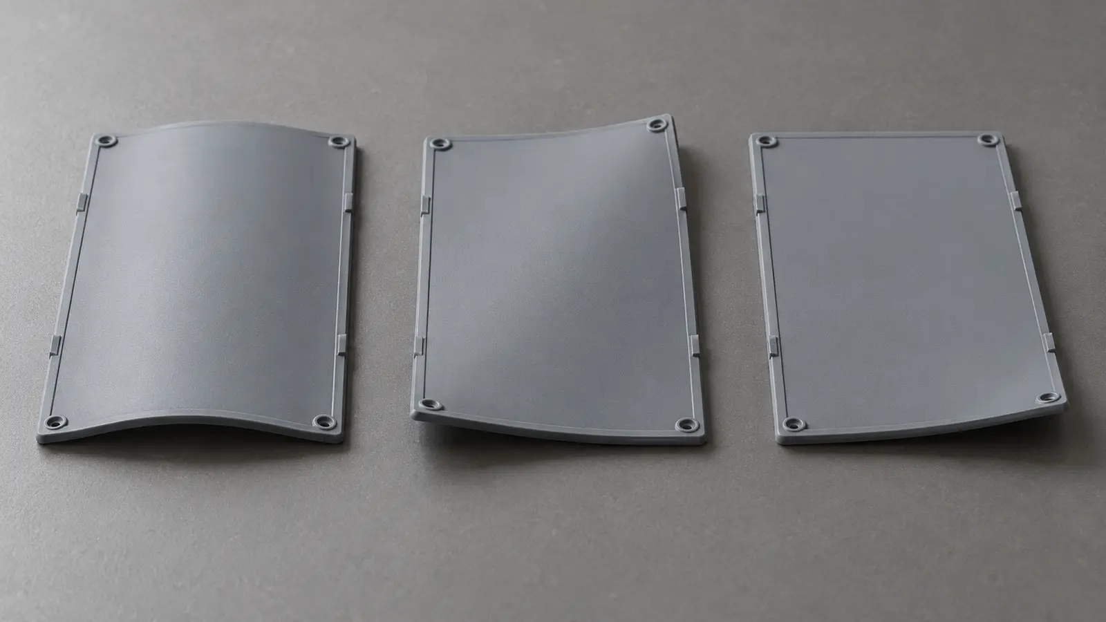
A warped edge is not the same as an incomplete edge. If a corner or rib never filled, start with Meco's short shot troubleshooting article instead. If the part is complete but the geometry moves out of shape, keep the warpage investigation focused on shrinkage, stress and cooling.
Take photos from a fixed angle and mark the direction of movement on the drawing. For flat parts, record where the part touches the reference surface and where it lifts. A simple record of direction can be more useful than a close-up photo that hides the full shape.
What causes warpage in injection molding?
Warpage usually comes from several connected factors rather than one bad setting. A useful review separates the problem into part geometry, mold cooling, packing and gating, material behavior, and process conditions.
Part geometry can create uneven cooling and stiffness
Large changes in wall thickness make it harder for the part to cool and shrink evenly. Thick corners, heavy ribs, solid mounting blocks and uneven wall transitions can hold heat longer than surrounding areas.
Stiffness matters too. A broad thin panel has less resistance to a small internal stress than a boxed section with ribs. Adding a rib can help the part resist bending, but an oversized rib can create a thick local section and introduce a different shrinkage problem. Geometry needs to balance cooling and structural support.
Symmetry also matters. An asymmetric cover with ribs only on one side may not shrink like a balanced plate. The design does not have to be visually symmetric, but the team should understand where stiffness and material mass differ across the part.
Cooling layout can create hot and cold regions
The mold must remove heat from the part, but cooling is rarely identical at every point. Deep cores, inserts, corners and areas far from a cooling channel can stay warmer.
A core side that runs warmer than the cavity side can make one face of a panel behave differently from the other. Local hot spots can also appear around steel features that are difficult to cool. Autodesk notes that temperature variation through the thickness and from region to region can contribute directly to warpage. [1][2]
Do not reduce this check to one machine display value. Mold temperature is a condition across the tool, not just a single setpoint. The toolmaker may need to compare actual temperatures, coolant flow and the cooling layout around the distorted area.
Packing and gate design affect shrinkage distribution
After filling, the machine uses holding or packing pressure to feed extra material while the part starts to shrink. That pressure has to travel through the gate and flow path.
If a thin section freezes early or the gate closes before a remote region is fully packed, one area can leave the mold with a different density from another. Autodesk's hold-pressure guidance notes that uneven pressure transfer during packing can contribute to differential shrinkage and increased warpage. [5]
Gate position also affects how far pressure must travel and how the material flows. Moving a gate may improve packing in one area while changing fiber orientation or the location of a visible gate mark. A gate change therefore needs a full part review.
Material behavior can change both shrinkage and direction
Different resin grades shrink by different amounts. Semi-crystalline plastics often have different shrinkage behavior from amorphous plastics, and fillers can change the picture again.
Glass fibers can lower shrinkage in one direction while increasing the difference between flow and cross-flow behavior. This can improve dimensional control in one design and make orientation-driven warpage more important in another.
Use the exact supplier grade, not only a family name such as PP, ABS or nylon. Meco's injection molding materials page groups the main resin families and provides a starting point for discussing grade choice. The actual grade data and the finished-part requirements still control the decision.
Process conditions can add or release stress
Melt temperature, mold temperature, injection speed, packing pressure, packing time and cooling time all influence the part's thermal and pressure history.
A very fast or very slow fill can change orientation and temperature along the flow path. Too little packing may increase shrinkage differences. Uneven mold temperature can lock in a bend. Ejecting while the part is still too hot can allow the shape to move more after release.
The settings interact, which is why a universal recipe is risky. A change that improves flatness can also cause flash, change dimensions or create a new surface issue. The useful goal is a stable process that meets the whole drawing and assembly requirement.
What should you check before changing molding settings?
Measure the problem before trying to fix it. A repeatable measurement method helps separate real molded warpage from handling, fixture force, conditioning or random sample variation.
- Define the reference condition. Decide how long after molding the part will be checked and at what agreed temperature or conditioning state.
- Measure the free part first. Do not clamp a flexible part flat and then use that clamped shape as proof that warpage is gone.
- Track the cavity. Keep multi-cavity samples separate so a local cooling or gate problem is not hidden in mixed parts.
- Mark the direction. Record which edge lifts, which wall bows and which datum or mating feature moves.
- Compare with the last accepted run. Review resin grade, fill time, pack settings, mold temperature, cooling time and any tool maintenance.
- Check the assembly requirement. Flatness matters because the part must seal, fit, align or look correct. Use the real function to decide how much movement matters.
If the deformation began after a material change, do not assume the new resin is the only cause. The approved process window may also need to change. If it began after mold work, check the cooling and insert condition around the affected area.
Meco's R&D engineering support is relevant when the team needs to compare a process trial with a design or tooling change before more steel work is committed.
For production programs, Meco's custom injection molding service connects the part review with tooling and molding.
Which process changes may reduce warpage?
Process changes are worth testing when the geometry and tool can make a balanced part but the current run is creating uneven temperature, pressure or stress. Change one main factor at a time where practical and keep the samples.
Balance mold temperature before chasing one number
Compare the cavity and core sides around the warped area. A large local difference may need attention in the cooling circuit, not simply a longer cycle.
A process engineer may adjust coolant conditions or mold temperature within the resin and tool limits. The goal is more balanced cooling, not the lowest possible mold temperature. A cold surface can freeze early while another area remains hot.
Review packing pressure and packing time
Packing can reduce regional shrinkage when pressure still reaches the area. More pressure is not automatically better.
If the gate has frozen or a thin section has already closed, extra holding time may not feed the remote region. A packing study can compare part weight, dimensions and warpage across controlled changes. Autodesk recommends packing-profile changes as one way to reduce differential shrinkage without immediately changing part geometry. [3]
Check filling speed and flow balance
Injection speed changes how quickly the flow front moves and can affect orientation, pressure loss and temperature. For glass-filled materials, changes in flow pattern can change the fiber direction that influences warpage.
Use a controlled speed profile rather than assuming faster is always better. If the part only becomes flat at an extreme setting that creates another defect or sits outside the resin supplier's guidance, the design or tooling needs attention.
Confirm cooling time and ejection condition
A part may continue to distort if it is released while one region is still much hotter than another. Additional cooling time can help some parts reach a more stable shape before ejection.
Longer cooling is not a cure for a poor cooling layout. If a local hot spot remains, extra cycle time may make production slower without removing the imbalance. Tool cooling may need review.
Warp still repeating? Send the part drawing, resin grade, marked samples and current process history so Meco can review cooling, packing, gate and geometry before the next trial.
Talk to an EngineerWhen should the part, gate or mold design change?
A design or tooling review becomes more important when the same distortion returns under a stable process, or when acceptable shape requires settings that create other defects. At that point, the geometry or heat-flow path may be setting the limit.
Make wall changes more gradual
More uniform wall thickness helps regions cool and shrink in a more similar way. Avoid adding a large solid block where a hollow feature or supported wall can do the same job.
This does not mean every wall must be identical. Functional loads, screw joints and sealing surfaces still matter. The design goal is to avoid unnecessary mass changes and to make the thermal path easier to control.
Use ribs to add stiffness without creating a heavy section
A thin broad panel may warp because a small stress can bend it easily. Ribs can raise stiffness without making the full wall thick.
Ribs still need a molding review. A heavy rib base can create a local thick section and increase sink or shrinkage risk. The rib layout should support the direction in which the part needs stiffness while keeping material buildup under control.
Review gate location with packing and orientation in mind
A gate controls more than where plastic enters. It influences the fill path, pressure distribution and orientation of the material.
If a long part twists in a repeatable direction, the gate strategy may be worth comparing in mold-flow analysis. Autodesk notes that gate changes can be used to influence orientation effects, but the modified design should be re-analyzed and then proven with real molded parts. [4]
Review the cooling layout around the problem area
If one side of the part runs hotter, a tooling change may be more reliable than extending cooling time for the whole cycle. The toolmaker can review channel location, inserts and other heat-transfer options.
Autodesk lists mold inserts as one option for changing local cooling and reducing differential shrinkage in some cases. [3] The exact solution depends on the tool construction, available space and the feature that is moving.
Reconsider the material only with the full requirement in view
A resin with more uniform shrinkage may improve dimensional stability, but material changes affect much more than warpage. Strength, impact response, chemical resistance, moisture behavior, appearance, cost and approvals may all change.
For fiber-filled grades, lower overall shrinkage does not guarantee lower warpage because directional orientation can become more important. Compare the actual grade and flow pattern instead of choosing material by one shrinkage number.
These choices are easiest before tooling is locked. Meco's turnkey injection molding guide explains how DFM, tooling, molding and later assembly can be coordinated in one program.
If the molded part is one component in a larger product, whole product manufacturing can keep the plastic geometry tied to the metal parts, fasteners and assembly checks around it.
How do you know the warpage fix worked?
A flatter sample is useful evidence, but the fix is successful only when the part holds the required shape, fits its assembly and repeats across production. Use the same measurement method before and after the change.
Measure at a consistent time
A part can continue cooling and relaxing after ejection. Choose an agreed time and conditioning state for comparison. Do not measure one sample warm at the press and another after several hours on a bench.
For moisture-sensitive plastics, conditioning can also affect dimensions. Record the state required by the drawing, material plan or customer specification.
Use the drawing datums and the free-state part
Flatness and profile depend on a reference. A coordinate measuring machine, fixture, surface plate, height gauge or other method may be appropriate depending on the geometry and tolerance.
The measurement method should not force the part into the desired shape. If the assembly itself is designed to restrain a flexible cover, the team should separately agree what free-state warp is allowed and what assembled fit must achieve.
Check the mating parts
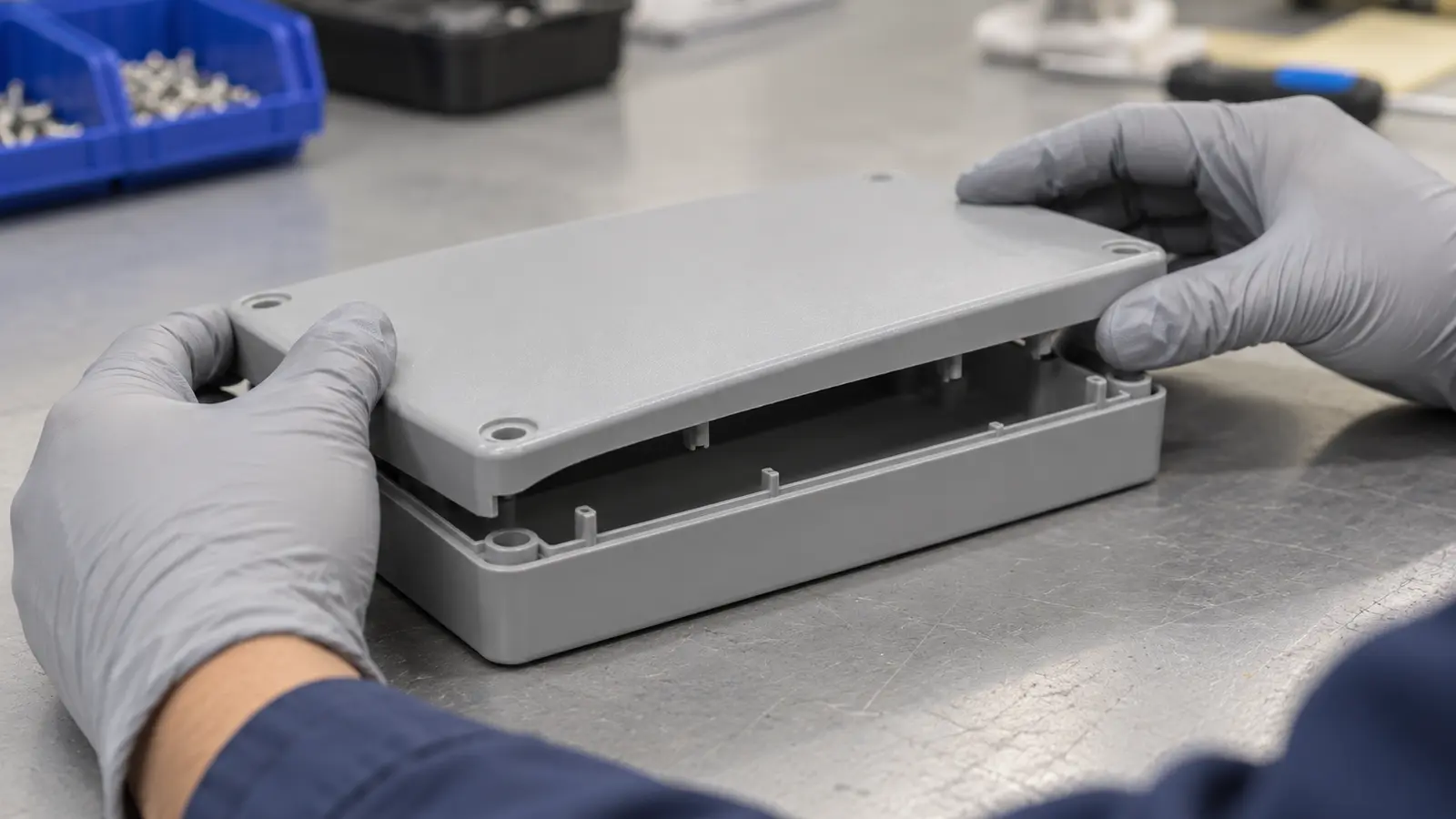
A housing can meet one flatness value and still miss a connector, gasket or screw hole. Assemble the part with the components it must fit.
Meco's product assembly services are relevant when molded components need fit and function checks with the rest of the product. Keep the assembly test tied to the actual product requirement, not only to a cosmetic impression of flatness.
For a broader look at locating, fastening and fit, Meco's mechanical assembly guide explains how separate components are joined and checked as an assembly.
Check repeatability, not one best sample
Keep samples from the required cavities and from a stable production period. Record resin lot, mold revision and the approved process settings.
If the change improves one cavity but another still moves, the process is not yet fully understood. If the part is flatter but flash appears or a thin feature becomes incomplete, the tradeoff also needs review.
Meco's flow-line guide and flash article show why one correction should not create a new defect elsewhere.
What should be agreed before production approval?
Set the shape requirement, measurement method and assembly checks before the process is approved. A phrase such as "part must be flat" is not enough for a part that can flex, condition or continue moving after ejection.
Identify the datums and surfaces that control fit. State whether the requirement is flatness, profile, hole position, gap at assembly or another measurable condition. Define when the sample is measured and whether it is checked free or in a fixture.
For a new design, review wall thickness, gate location, cooling access and resin behavior before the mold is built. Meco's injection molding partner checklist gives buyers a wider set of questions about DFM, tooling ownership, quality records and production support.
Keep an approved sample and the inspection record with the released setup. If a later resin, tool or process change can affect shrinkage or orientation, repeat the agreed checks before accepting the change.
Discuss your molded part
Share the drawing, exact resin grade, photos of the warped shape and the way the part is measured. Meco can review the likely sources of uneven shrinkage and help the team choose the next process, tooling or design check.
- Design review. Wall thickness, ribs, gate-sensitive areas and flatness-critical features.
- Process review. Packing, mold temperature, filling and cooling conditions.
- Material review. Resin grade, fillers and orientation risk.
- Quality support. Sample measurement, fit checks, FAI, PPAP and CMM records.
References and sources
External technical references rechecked 16 October 2026.
- Autodesk. Injection Molding: The Causes of Warpage. Simulation Blog, 3 June 2020.
- Autodesk Moldflow Insight Help. Warp analysis. 2024 documentation.
- Autodesk Moldflow Insight Help. Reducing warpage due to differential shrinkage. 2024 documentation.
- Autodesk Moldflow Insight Help. Reducing warpage due to orientation effects. 2024 documentation.
- Autodesk Moldflow Insight Help. Hold pressure result. 2026 documentation.
