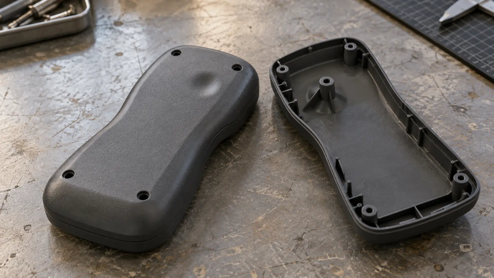
Injection molding sink marks are shallow dips on a plastic part, often opposite a thick wall, rib or screw boss. Start by locating the dip and checking whether it repeats, then review wall thickness, packing and local cooling before choosing a fix.
A process adjustment may help if the cavity is not packed long enough. If the same thick feature keeps sinking under stable conditions, a change to the part or mold may be the more reliable answer.
A handheld controller cover can look smooth in the CAD model and still show a shallow dip after molding. A sink mark may affect appearance, and its location can matter if the surface must meet a gasket, align with another part or meet a visible finish requirement.
The location is a useful clue. A dip on the outside of a molded part may sit opposite a rib, screw boss or thick wall on the inside. If the same mark appears in the same place across repeated shots, look at the geometry and process together. The injection molding defects guide provides a broader overview of common molding issues.
This guide explains what sink marks are, why they form, and how to investigate practical process and design fixes. It also covers how to distinguish them from other defects and how to agree on acceptance criteria before production.
Key takeaways
- A sink mark is a shallow surface depression linked to local shrinkage, often opposite a thick feature.
- Wall thickness, packing access, gate freeze and local cooling can all affect the result.
- Record the part location, cavity, resin grade and process conditions before changing settings.
- Controlled trials can help, but a persistent heavy section may need a design or tooling review.
- Approve the full part for appearance, fit and dimensions, not just the visible dip.
What are injection molding sink marks?
Injection molding sink marks are shallow depressions or dimples on a molded plastic surface. They often form over a thicker section, such as a rib, boss or wall transition, as the material cools and shrinks. Autodesk describes sink depth as a surface result that can vary with local geometry and appearance conditions.[2]
The dip can appear on the opposite face from the heavy feature. Its depth and visibility may depend on the resin, surface texture, color and lighting, so two parts with similar geometry may not look identical. A mark is not automatically a functional failure, but it should be checked against the part’s appearance and dimensional needs.
If you need a refresher on how resin fills a mold and cools into a part, see this plastic injection molding explanation.
How does a sink mark form after the mold fills?
A sink mark forms when material inside a thicker area shrinks as it cools, while the outer surface has already started to solidify. The shrinking core can pull the skin inward and leave a shallow depression. Autodesk’s troubleshooting guidance connects sink marks with shrinkage, thick sections, packing and gate freeze.[1]
Plastic shrinks as it changes from a hot melt into a solid part. Thin areas often cool sooner than thick areas, so a heavy feature can keep contracting after the nearby surface has become firm. If the cavity cannot feed additional material into that area at the right time, the surface may move inward.
Why packing and gate freeze matter
After the mold cavity fills, holding pressure helps feed more material into the cavity to compensate for shrinkage. This stage is often called packing or holding. The gate is the path through which the melt enters; once it freezes, additional material can no longer reach the part through that gate.
If the gate freezes before a thick region has received enough material, more hold time or a higher machine setting may not solve the problem. The pressure setting alone does not show whether pressure reaches a distant feature while the gate is still open.
That is why a sink mark should be investigated as a local part-and-process issue. A process setting may help when the cavity is under-packed, but the location, geometry and timing of gate freeze also matter.
Where do sink marks usually appear?
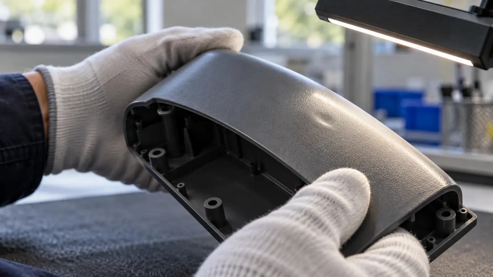
Sink marks often appear above ribs, screw bosses, thick corners and changes in wall thickness. These features create areas where more plastic collects, cools more slowly or shrinks differently from the surrounding wall.
Above ribs and screw bosses
A rib supports a panel, while a screw boss provides material around a fastener. If either feature is too thick at its base, it can create a heavier local section than the visible wall. The outside face may then show a depression directly opposite the feature.
Look at both faces of the part. A surface dip may be difficult to interpret on its own, but matching its location to the rib or boss on the reverse side helps identify a likely geometry connection.
At thick corners and wall transitions
A thick corner can hold heat longer than a nearby flat wall. An abrupt change from a thin wall to a much thicker section can create a similar difference in cooling and shrinkage.
Section views can reveal material buildup that is hard to judge from a surface image. The drawing and the molded part should be reviewed together, especially when a dip repeats in one location.
How can you tell sink marks from other defects?
A sink mark is a shallow depression in a surface. Other defects may look uneven too, but their shape and location can point to a different cause. Compare what the part actually shows before changing a process setting.
| What you see | Likely issue | Useful distinction |
|---|---|---|
| Shallow dip over a boss or rib | Sink mark | Surface is locally pulled inward after filling. |
| Rib or corner is not fully formed | Short shot | Material never filled that feature completely. |
| Wavy bands or gloss changes | Flow lines | Pattern may follow melt movement, without a real dent. |
| Thin extra lip at an edge | Flash | Material extends beyond the intended outline. |
| Whole panel bows or twists | Warpage | Shape changes over a broader area, not just one spot. |
| Internal hollow not visible outside | Void | Needs suitable inspection to confirm; not judged by appearance alone. |
Meco has separate guides for short shots, flow lines and injection molding flash. Those articles deal with different problems. A knit line forms where separate flows of plastic meet, often near a hole, rather than because a thick area sinks. For a sink, a repeated dimple above a heavy feature is a more useful starting point than the word “defect” alone. Learn more about a knit line.
What causes sink marks in injection molding?
The usual causes fall into three connected areas: local part thickness, how much plastic can be packed into the cavity, and how evenly the part cools. Material choice can change the result too.
Thick areas need more time to cool
The center of a thick wall holds heat for longer. A rib that is too heavy at its base can make the nearby panel behave like a much thicker section. The outer skin then has to follow the shrinkage below it.
A product drawing may show the finished shape but not make this risk obvious. A section view through the rib or boss helps show the real amount of plastic in one place. Checking that section is often more useful than looking only at the surface dent.
Packing pressure may not reach the area
Packing pressure is the force used to feed material after filling. If it is too low, or stops too early, the part may not receive enough extra plastic to balance shrinkage. But a high setting at the machine does not prove that pressure reaches every thick section.
A small gate, a long flow path or a narrow connecting wall can limit how long an area remains open to packing. When the gate freezes, a remote heavy feature cannot receive more melt. Raising pressure after that point may do little for the mark.
Cooling can be uneven
The two mold surfaces may not stay at the same temperature. A deep steel feature may also cool differently from a flat cavity wall. Hot spots can keep local plastic soft longer and change how much it shrinks.
Cooling is not simply “make everything colder.” A much colder surface may set early while the center still contracts. Engineers need to compare actual mold conditions, the resin supplier’s limits and the time the part spends cooling.
The resin grade matters
Different plastics do not shrink by the same amount, and additives can change their behavior. A grade with glass or mineral filler may respond differently from an unfilled grade. The grade, filler level, color package and approved processing range should be recorded before making comparisons.
This is also why changing material to hide a sink cannot be treated as a cosmetic-only fix. Strength, stiffness, impact response, dimensions and regulatory needs may change. A new grade requires its own design and production checks.
What should you check before changing the process?
Save the evidence first. A clear pattern can help the engineer decide whether to test packing, cooling or the shape of the part.
Do not compare random parts taken from different cavities or different stages of startup. If the mold has more than one cavity, identify which one made each sample. Record the exact resin and any recent changes to the tool, material or machine setup.
- Locate the dip. Mark the spot on a photo and the part drawing. Check the back for a rib, boss, corner or wall change.
- Compare several shots. Is the dip always in the same position and about the same size? Does it change after the mold reaches steady temperature?
- Check the approved process record. Review actual fill, pack and cool conditions against the last good run and the material data sheet.
- Look at the gate and flow path. Ask whether the heavy region can still receive pressure during packing, or whether melt access closes too soon.
- Check the required function. Determine whether the affected face is decorative, a sealing land, a snap-fit area or a dimension that controls assembly.
These checks help separate a repeatable geometry issue from a process change. For difficult parts, Meco’s R&D engineering support covers design review, prototyping and production planning. It is the stage to compare a process trial with a possible design change.
Which process changes may reduce sink marks?
Process changes are worth testing when the part can still be packed correctly and the geometry is not forcing a large local shrinkage. The right trial depends on the recorded cause.
Review holding pressure and time
A process engineer may test holding pressure and holding time in controlled steps while checking the full part. Enough packing can reduce a local depression, but excessive packing may cause flash, stress or a size change elsewhere.
A gate-freeze study can help set useful holding time. One method compares part weight at increasing hold times under controlled conditions. When weight no longer rises, extra hold time may not be feeding more material. The method needs the engineer’s judgment and a stable process.
Check mold and melt temperatures separately
Melt temperature describes the hot plastic; mold temperature describes the tool. Both affect how resin fills, packs and cools. A warmer melt may change the way a narrow area fills. A different mold temperature may change how soon the skin becomes firm.
Neither value should be raised or lowered on its own without checking the material limits. Temperature changes can affect cycle time, dimensions, surface quality and other defects. The best condition is not always the coldest or hottest one.
Confirm cooling time and local balance
If parts leave the mold while a heavy section is still too hot, a depression may become more visible as cooling continues. Extra cooling time can help in some cases, but it does not remove the underlying material buildup.
If one area remains hotter than the rest, the toolmaker may need to review the cooling layout or temperature control. A balanced tool often matters more than a large change to one machine number.
After each trial, check the full part for new flash, short shots or size changes. Meco’s flash troubleshooting article explains why chasing one problem with pressure alone can create another.
Need a second look at the cause? Send the part drawing and marked samples. Meco can review the resin, affected geometry and available process information before suggesting a practical next check.
Talk to an EngineerWhen does the part or mold design need to change?
A design review becomes important when the same heavy section keeps sinking after reasonable, stable process trials. Geometry may set a limit that packing alone cannot overcome.
Reduce thick material without removing the needed support
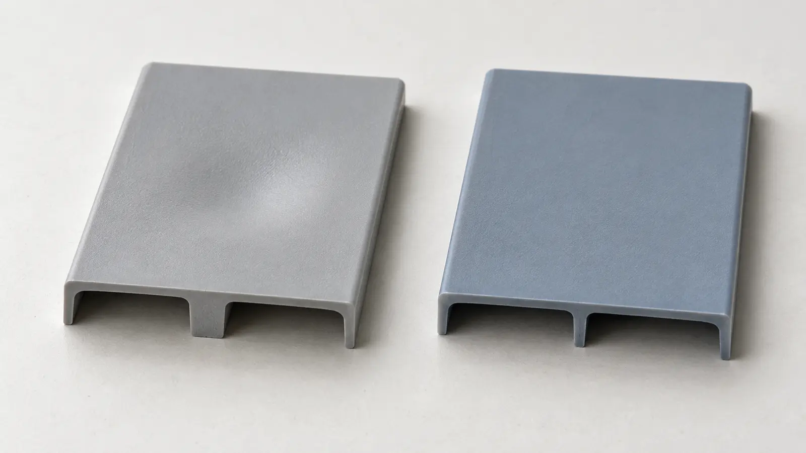
Coring out means replacing a solid thick region with a hollow shape where the part allows it. A tall, solid mounting post may sometimes be changed to a hollow boss. A thick block used for stiffness may be replaced with a thinner wall supported by ribs.
These changes are not a simple order to make every feature thinner. A screw boss must still hold its fastener. A rib must still support the panel. The team has to protect the load path, assembly fit and minimum strength while reducing the hot, heavy section.
Review rib roots, boss bases and wall transitions
A rib usually works better as a thin support than as a heavy solid wall. The correct rib base thickness depends on the material and overall wall thickness, so one universal percentage should not be applied to every resin and feature.
Use a section view through the most visible sink to check where the material builds up. A gentler transition or a smaller local mass may help the wall cool more evenly. But a sharp corner added to save material can create stress, so the final shape needs design review.
Decide whether the gate or cooling layout is limiting the fix
Even a good part design may be hard to pack if the gate closes before the thick area receives enough melt. A different gate size or position may help, but it can move the gate mark or change the flow path. A tool modification needs a wider part review.
Some tooling updates involve machining a cavity or insert. Meco’s CNC machining capability is relevant to precision metal component work, while the custom injection molding service covers the tool-and-molding program itself. The team must still confirm which changes are feasible for the actual mold.
This choice is easiest before steel tooling is finished. If the part is already in production, compare the expected improvement with the change cost, tool downtime and need to approve samples again. A cosmetic gain is not useful if it makes assembly or strength worse.
How do you know the sink-mark fix worked?
A flatter surface is encouraging, but the change is successful only when the full part still meets its agreed requirements.
First repeat the original appearance check. Use the same light, angle and distance. Keep marked before-and-after samples from known cavities. A clear photo is useful, but it should not replace an agreed acceptance sample or drawing requirement.
Next check the dimensions and use of the part. A cover may need to sit flat against a gasket, keep its screw holes aligned and hold a snap feature. The depression could look smaller while a fit or sealing problem remains.
Record the material grade, mold revision, tested process settings and inspection results. If a setting change creates new flash or makes a thin edge incomplete, that tradeoff must be included in the decision. A trial passes when it meets the whole specification, not just one cosmetic target.
If the change affects how a component fits with others, review it during assembly. Meco’s product assembly services connect molded components with final fit and function checks. For a larger program, whole product manufacturing links engineering, component production and assembly planning.
What should be agreed before production approval?
Set the appearance limit and the functional checks before approving the process. A clear acceptance rule avoids treating every faint dip as a failure or ignoring a mark on a critical feature.
Identify the surfaces that must look flat, the allowed comparison standard and the dimensions that control fit. State how samples will be viewed and measured, including which cavities and production conditions matter. Keep approved samples so later lots can be compared fairly.
For new designs, an early design-for-manufacturing review can catch heavy ribs and bosses before tooling decisions are fixed. Meco’s injection molding partner checklist helps buyers ask how a supplier handles tooling, design feedback and quality records.
Meco supports over 50 resin options and links molding with related production services. Those capabilities help a team review options, but no general resin count or standard tolerance is a sink-mark acceptance limit. The drawing, material grade and intended use must still set the standard.
If the part belongs to a larger assembly, use the same acceptance plan from trial samples through production. The turnkey injection molding guide explains how tooling, molding and later steps can be coordinated within one program.
Discuss your molded part
Share the 3D model or drawing, resin grade, marked photos and sample history. Meco’s engineering team can review the likely source of a sink and discuss whether process, part or tooling changes deserve the next test.
- DFM feedback. Local wall, rib and boss geometry.
- Molding review. Gate access, packing and cooling questions.
- Quality checks. Appearance, fit, dimensions and approved samples.
- Production support. Molded components and downstream assembly needs.
References and sources
- Autodesk, Moldflow Insight Help. “Troubleshooting sink marks and voids.” Describes shrinkage, early gate freeze, packing and design-related sink causes. Open source
- Autodesk, Moldflow Help. “Sink marks, depth result.” Explains that visible sink depth depends on local geometry and surface appearance. Open source
