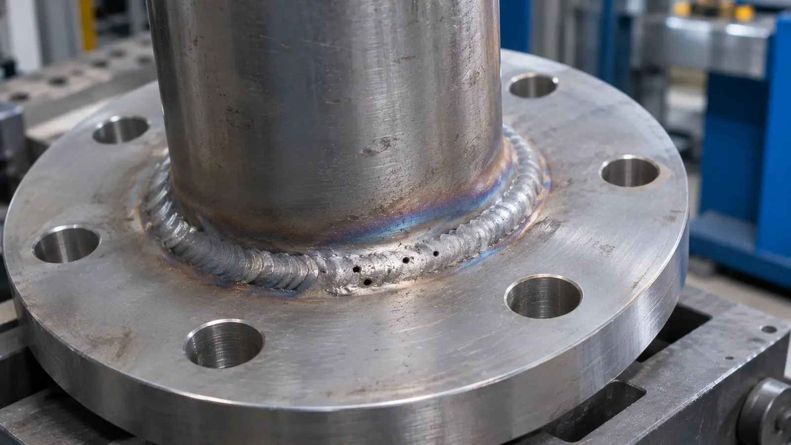
Weld porosity can appear as tiny holes on a bead, but the biggest concern may be pores hidden inside the metal. A visible pit is a reason to investigate, not enough evidence to decide whether the joint will fail.
Start by recording where the pores appear. Then check cleaning, moisture, gas coverage, and the job's acceptance rules before choosing further testing or repair.
A welded steel bracket may look sound until someone notices small round pits along one joint. Another bracket from the same batch may look smooth. Those two surfaces do not tell the whole story about what is inside the weld.
The useful question is not just, "Why are there holes?" It is also, "Where are they, what may have caused them, and what does this joint need to do?" The answers guide both inspection and prevention.
This article deals with gas-related pores in welded metal. For an overview of MIG, TIG, and other joining methods, Meco's types of welding guide explains how those processes differ. Here, the focus stays on finding and preventing one specific flaw.
The same basic logic applies to a steel frame, a stainless enclosure, or an aluminum housing. The likely gas source and best checks can change with the material, process, and joint design.
Key takeaways
- Visible holes are only part of the picture. A smooth weld can still contain internal pores.
- The pore pattern is a clue, not a diagnosis. Small scattered pores, grouped pores, and long cavities can point to different conditions.
- Cleaning and shielding matter. Oil, moisture, coatings, poor gas coverage, and consumable condition are common starting points.
- Inspection must match the risk. Visual checks cannot measure hidden porosity; radiography or another qualified method may be needed.
- Fix the cause, then prove the fix works. A cleaner-looking bead alone does not confirm the next weld meets the required standard.
What is weld porosity and how does it form?
Weld porosity is a group of small spaces left in solid weld metal when gas becomes trapped during cooling. Those spaces may be open at the surface or sealed below it.
A weld pool is the small area of liquid metal made by the heat of welding. While it is liquid, gas can enter from the air, from moisture or other material on the joint, or from the welding process. Some of that gas forms bubbles.
If a bubble reaches the top while the pool is still liquid, it can escape. If the metal freezes around it first, the empty space stays in the bead. Many small spaces form scattered porosity. Larger or connected spaces can create a different pattern.
It helps to separate porosity from other marks. Spatter is metal thrown onto the area around a weld. Undercut is a groove beside the bead. Lack of fusion means metal did not join where it should. None of those is simply another name for a gas pore.
These are separate problems with separate causes. For a wider view of other flaws and inspection limits, see Meco's welding defects guide.
What types of weld porosity can appear?
Porosity is described by where the cavities are and how they are arranged. That makes a photo, a section view, or an inspection image easier to discuss without guessing the cause too early.
Surface pores versus internal pores
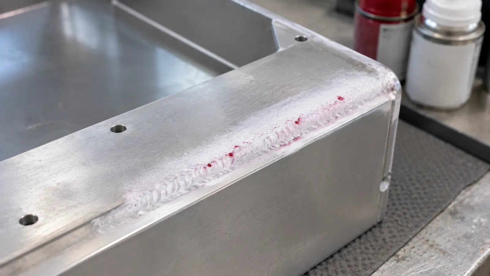
Surface porosity leaves round openings or pinholes that an inspector can see. Internal porosity is below the surface, so even a smooth bead may contain empty spaces. The number of visible pits cannot be used as a direct count of hidden pores.
For example, a fillet weld joining two sides of a steel bracket may show several holes at its edge. That may justify checking how the joint was cleaned and protected, but it does not show the total amount of porosity in the weld.
Scattered, grouped, linear, and elongated pores
Pores can be spread through a weld or gathered in one area. An elongated pore is longer than it is wide. Some long, tube-like pores are called wormholes. They can occur when gas is made in a narrow space and becomes trapped as metal freezes.
| PATTERN | WHAT IT LOOKS LIKE | WHAT IT CAN SUGGEST |
|---|---|---|
| Surface-breaking pores | Round pits open to the bead surface | Gas reached or opened at the surface; internal conditions may also need review. |
| Distributed porosity | Many separate, small pores across the weld | A gas source affecting much of the weld, such as unstable shielding or moisture. |
| Clustered or linear pores | Pores grouped together or following a line | A local condition or repeated source. Location matters more than the label alone. |
| Elongated pores / wormholes | Long cavities or a chain-like pattern | Large gas release or trapping in a joint gap, often linked to contamination or coating. |
An X-ray image may show patterns that cannot be seen from outside the part. Still, no pattern proves one cause by itself. The next step is to connect the appearance with the material, weld location, and process record.
Why does porosity matter for weld quality?
Pores leave less solid metal to carry a load or seal a joint, but not every pore makes a weld unacceptable. The effect depends on size, number, location, and what the finished part must do.
Think of a welded support that holds a machine cover. A few tiny internal pores may have a different effect from a large group of pores in a joint that carries repeated loads. Fatigue means damage that builds when a part is loaded again and again.
Pores near a loaded area may help a small crack start over time. For a sealed tank or enclosure, a path of connected pores could be a leak concern. A decorative part may have a different risk, although appearance can still matter.
A pore is therefore an indication to evaluate, not an automatic rejection. Acceptance limits belong to the drawing, project requirements, and applicable welding code. A general online rule about the number of holes cannot replace those documents.
TWI's work on aluminum welds also shows why the amount and location of porosity matter to strength and fatigue. The same numerical effect should not be assumed for every metal or welded design.
What causes weld porosity?
The cause is usually a gas source, a condition that traps bubbles, or both. Checking these separately is more useful than changing welding settings without evidence.
Moisture, oil, coatings, and dirty joint surfaces
Water, grease, oil, rust, paint, and some surface coatings can add unwanted gas or interfere with the joint during welding. Heat can break down these materials and release gas directly into the molten metal.
A sheet-metal cover, for example, may arrive with cutting fluid left near the seam. Its surface can look dry while a thin film remains. Cleaning the joint edges with the approved method before welding reduces that source.
A coating must not be treated like bare metal. Some primers are designed for welding under stated conditions, but a thick or unsuitable coating can create more gas. Follow the material and coating instructions, including fume controls.
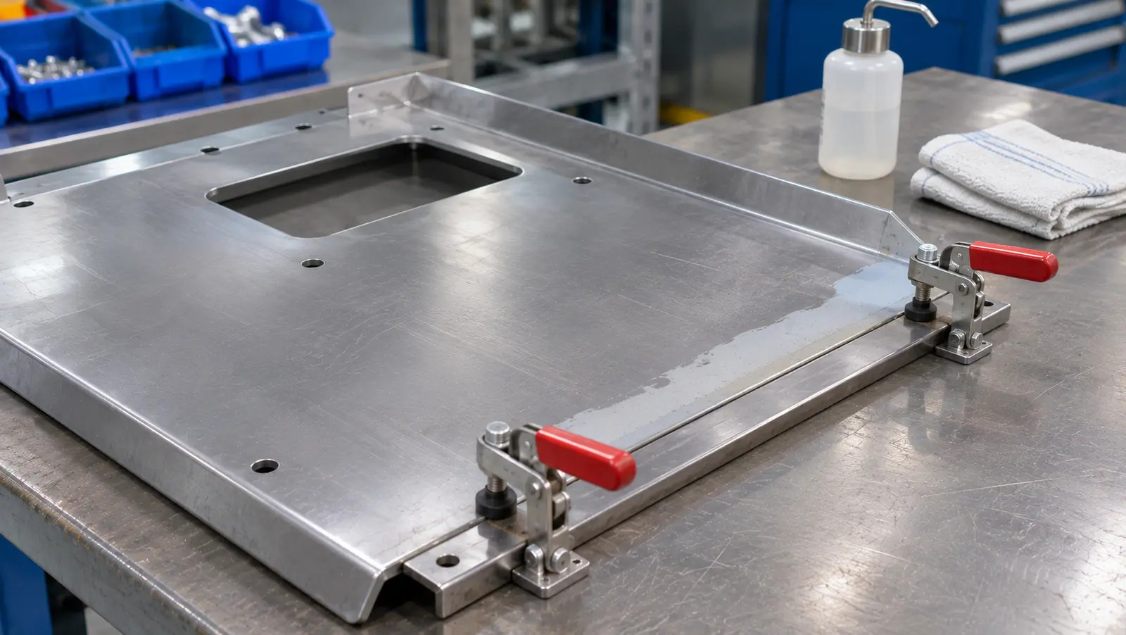
The material and joint shape both matter. Our sheet metal basics guide explains why thickness and fabrication conditions differ across common sheet products. Those differences also affect how a joint should be prepared.
Shielding gas problems
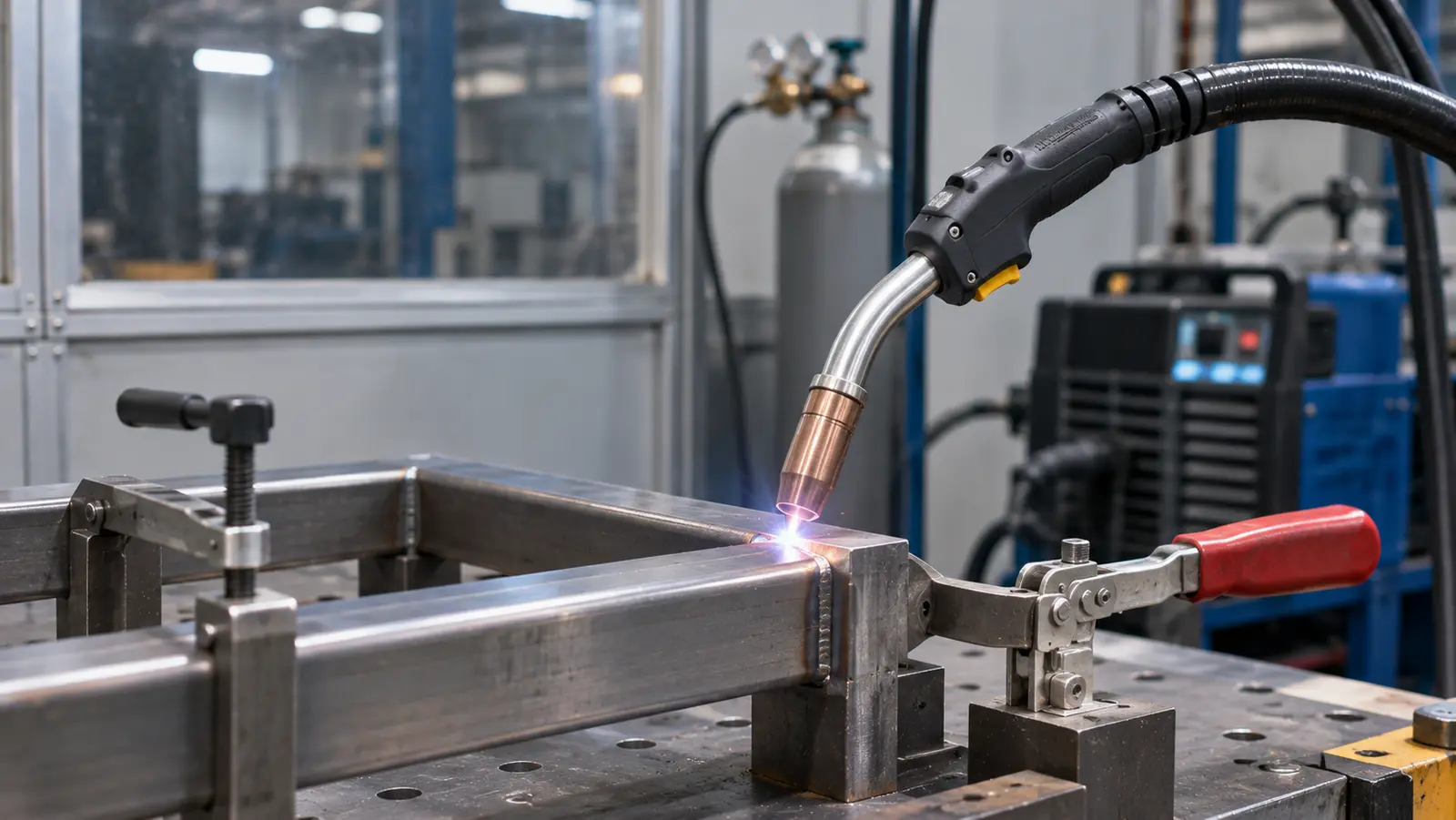
Gas metal arc welding (GMAW, often called MIG) and gas tungsten arc welding (GTAW, often called TIG) use shielding gas to keep surrounding air away from the hot weld pool. Poor coverage allows unwanted gases to enter.
Check the gas supply, line connections, flow setting, torch distance, nozzle condition, and drafts near the joint. A leak can reduce protection. So can a blocked nozzle or a strong fan blowing across the work area.
More gas is not always the answer. Excessive flow can create turbulence and pull air into the protective gas stream. The correct flow and torch setup come from the qualified welding procedure and equipment guidance.
For the process context, Meco's gas shielded welding services page explains the joining capability. This article focuses on how shielding faults can become porosity and how to verify the correction.
Filler material, storage, and the base metal
Filler wire and electrodes add metal to the joint. If their surfaces carry moisture or oil, that material can enter the weld pool. Flux, the material that protects some welding processes, also needs suitable dry storage where the process requires it.
Aluminum deserves special care. Its surface quickly forms an oxide layer, and moisture or other contamination around that layer can add hydrogen. The gas behavior of molten aluminum makes it more open to porosity than many people expect.
Cleaning, suitable filler handling, and a stable gas cover are more useful than blaming the aluminum grade alone. Meco's TIG welding service page gives process background, but the cleaning and inspection plan must still match the actual material and job.
Joint access, weld-pool behavior, and process stability
A narrow gap or tight corner can trap contaminants and gas. A changing arc, uneven wire feed, or unsuitable travel conditions can also affect how bubbles move through the liquid metal.
For instance, a T-joint with coating left inside a narrow corner can release gas while both sides are being welded. That is not the same issue as an open butt joint, even if the finished bead looks similar.
These factors work together. A team should check the qualified procedure and actual equipment setup instead of applying a single current, voltage, or gas-flow number to every weld.
How can you trace the likely source of porosity?
Start with what changed and where the pores repeat. The pattern narrows the search, but a controlled check is needed before naming the root cause.
A useful first record includes the part number, material grade, joint position, weld location, filler batch, gas setup, cleaning method, and drawing revision. It should also note whether the fault appeared after a shift, material batch, or equipment change.
| OBSERVED CLUE | FIRST THINGS TO CHECK | WHAT THE CLUE DOES NOT PROVE |
|---|---|---|
| Pores appear after a new batch arrives | Surface oil, primer, storage conditions, and cleaning records | That the base metal itself is defective. |
| Pores repeat near one corner or gap | Joint access, trapped coating, fit, and torch position | That every weld uses the wrong gas flow. |
| Pores begin after a gas cylinder or line change | Supply, connectors, leaks, nozzle, and shielding coverage | That increasing flow will solve the problem. |
| Only one work area is affected | Local drafts, gun condition, and setup differences | That the welding process is unsuitable for the product. |
| Pores persist after surface cleaning | Consumables, gas protection, parameters, and hidden contamination | That a smooth test bead confirms sound internal metal. |
Consider a hypothetical batch of steel support brackets. Small pores appear only on one fillet weld after a new fixture is installed. The team first compares joint access and cleaning around that fixture with the last accepted batch.
If the change caused a hard-to-reach corner, the corrective action may be better access and preparation. If the setup is unchanged, gas supply or consumables may deserve closer study. Either way, the team should test the suspected cause rather than assuming it.
Not sure what the pores mean? Share the drawing, joint details, material, and inspection concern. Meco can discuss a suitable manufacturing and quality review.
Talk to an EngineerHow are surface and internal pores inspected?
A surface check shows only what is open and visible. Internal porosity needs a method that can examine below the bead when the job requires it. The selected test must work for the material, thickness, and joint shape.
Begin with visual testing
Visual testing (VT) means looking closely at the weld under suitable lighting. It can find open pinholes, raised areas, and obvious surface changes. Good photos, location notes, and measurements help the quality team compare similar parts.
Yet a neat bead is not proof of a sound interior. A tiny visible hole might also lead to a deeper cavity. The inspector should not use appearance alone to accept or reject a weld with important load or sealing requirements.
Use a suitable method to check hidden spaces
Liquid penetrant testing (PT) can help reveal some openings that reach the surface of a suitable, nonporous material. It cannot show sealed pores deep inside. The surface must be prepared correctly for the test to work.
Radiographic testing (RT) creates an image using X-rays or other radiation. It is often useful for finding and showing gas cavities inside weld metal. Ultrasonic testing (UT) uses sound waves to find internal indications, but very small or scattered pores may be harder to assess with some UT methods.
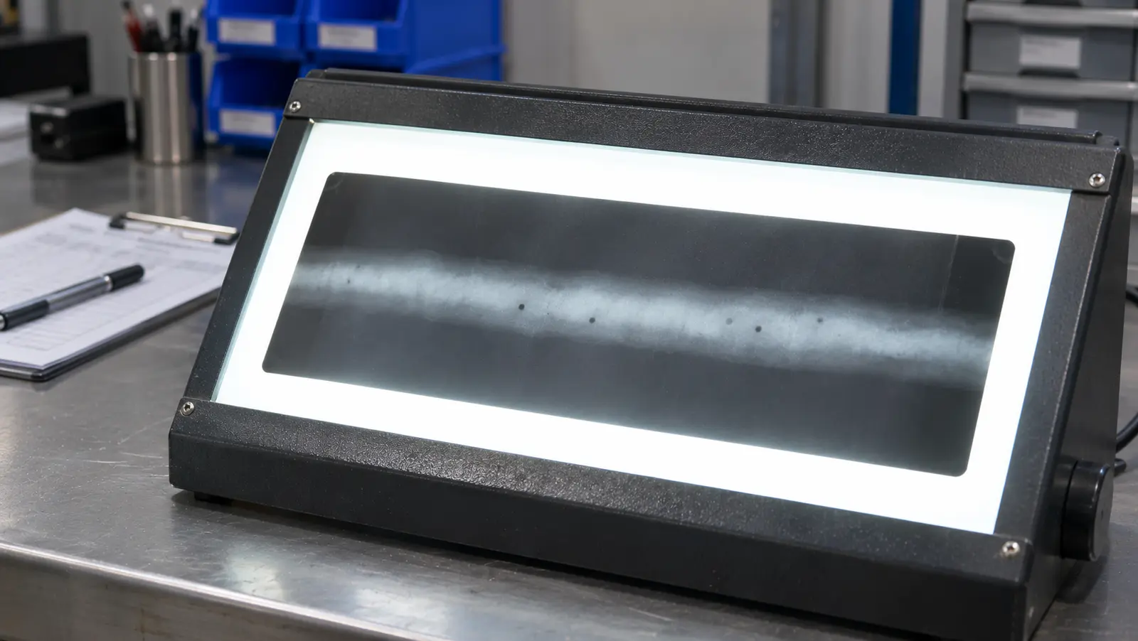
Neither test finds everything in every joint. Thickness, access, metal type, pore size, and the inspection procedure all affect results. The American Welding Society outlines these differences in its guidance on nondestructive weld examination.
Compare the results with the required acceptance rules
The inspector needs the customer drawing, the agreed inspection plan, and the relevant code or specification. An indication may be acceptable on one part but not on another with different service loads or quality rules.
Do not add a universal pore-size threshold here. That could lead someone to accept a weld without knowing the correct standard. If the test is inconclusive, the right response is an engineering review, not an estimate from a photo.
How can manufacturers prevent weld porosity?
Prevention works best when each known gas source has its own control, followed by a check that the process remains stable. A checklist is useful because cleaning, gas, filler, and joint setup are easy to review in the same order every time.
Control the conditions before welding
- Prepare the joint. Remove unwanted oil, moisture, loose oxides, and coatings from the required weld zone using approved methods. Confirm any weldable primer is within its stated limits.
- Protect consumables. Keep wire, electrodes, and flux in the condition required by their supplier and the welding procedure. Replace material that may have become contaminated.
- Confirm access and fit. Make sure the joint and fixture let the torch reach the weld zone. Look for gaps or pockets where coatings and gas may remain.
- Check the shielding system. Verify the supply, connections, flow, nozzle, and work-area drafts for gas-shielded methods. Use the correct procedure values rather than a generic setting.
Meco's custom fabrication and welding capabilities cover cutting, forming, welding, and related production work. The key planning point is that joint preparation and assembly fit should be reviewed as part of the complete build, not only at the welding station.
Keep the process stable while welding
During welding, a stable arc, consistent wire feed, suitable torch position, and controlled travel can help gas escape before the pool freezes. The right combination depends on the selected process, metal, thickness, and qualified welding procedure.
Changing several settings at once makes it hard to know what solved the issue. A controlled trial that changes one suspected cause and keeps the other conditions the same gives better evidence.
Verify the correction on real production conditions
After a change, inspect a test or first-off weld made with the intended part, fixture, material, and procedure. Record the result and use the same inspection standard that will apply to production.
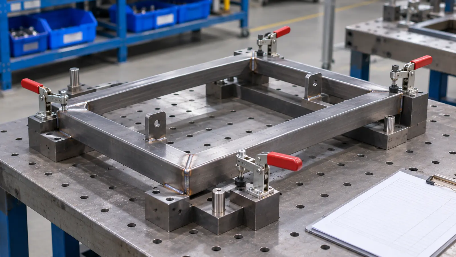
If internal soundness is a requirement, checking only surface appearance is not enough. Repeat results across suitable samples or production checks before deciding the fix has reduced the risk.
A new welded enclosure also needs to fit its other components. Meco's sheet metal assembly guide explains how cutting, bending, welding, and joining choices come together in one manufactured assembly.
What should you do if porosity is found after welding?
Do not cover, grind, or repair the indication before the part is evaluated. First decide what is present, what the joint must meet, and whether further examination is needed.
- Hold and identify the affected work. Record the part, weld position, and any related batch or process information.
- Check the acceptance requirement. Compare inspection evidence with the approved drawing, code, and project criteria.
- Choose the disposition. An authorized quality or engineering reviewer decides whether to accept, inspect further, or repair under an approved method.
- Control any repair. If removal and rewelding are required, use a qualified procedure and confirm the affected material has been properly addressed.
- Check the next production parts. Verify the cause has been controlled so the same pores do not return.
Grinding can erase the opening at the surface yet leave deeper pores behind. It may also remove weld metal that the design needs. TWI advises suitable examination and controlled removal when repair is needed, rather than assuming surface cleanup is enough.
A repair may also affect fit or the next assembly step. Meco's mechanical assembly guide describes why joining quality and part fit must be considered together in OEM products.
What information helps an engineer review the problem?
A useful request describes the part and the evidence, not only the word "porosity." That gives the reviewer a better starting point for inspection and process planning.
Include the material, thickness, joint type, drawing or weld symbol, welding method, production quantity, and any required test. Add clear images and mark where pores were seen. If possible, note when the problem first appeared and what changed.
For a new product, an early design for manufacturing review can also check joint access and inspection needs. Meco's R&D engineering services cover design, prototypes, and production planning, while the agreed job standard still controls final weld acceptance.
Meco works under an IATF 16949:2016 certified quality system. That supports controlled manufacturing work, but it is not a blanket approval of a weld or a replacement for the applicable welding code.
Plan a More Reliable Welded Part
Share your drawing, material, joint conditions, expected quantity, and any porosity or inspection concerns. Meco can review manufacturability and discuss a practical quality plan for the work.
- Part information: drawing, grade, thickness, quantity
- Joint details: weld type, access, fit, filler or gas notes
- Quality needs: inspection plan, relevant code, acceptance criteria
- Evidence: photos, location of pores, previous test results
References and sources
- The Welding Institute (TWI). Porosity in Welding - Defects / Imperfections in Welds.
- The Welding Institute (TWI). How Can Weld Porosity Be Detected and How Can It Be Remedied?.
- The Welding Institute (TWI). Avoiding Porosity When Welding Aluminium.
- American Welding Society (AWS). B1 Committee on Methods of Inspection.
