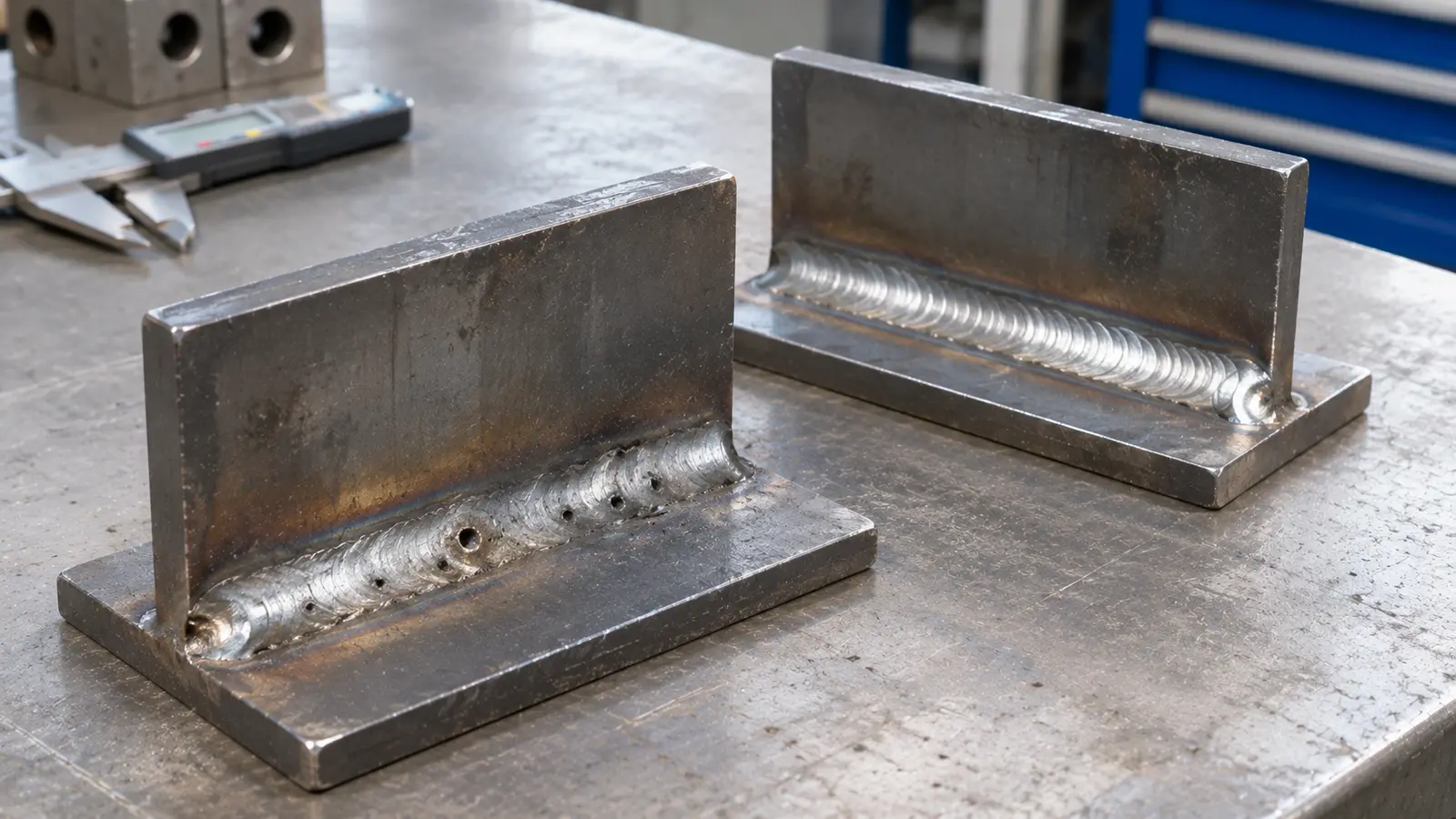
Welding defects are changes in a welded joint that may affect its strength, shape, seal, or fit. Common examples include porosity, undercut, lack of fusion, overlap, spatter, burn-through, and welding distortion. Some problems show on the surface, while others need further testing to find.
A mark is not automatically a failed weld. The drawing, service conditions, and applicable acceptance rules decide whether a particular imperfection is acceptable.
A weld joins metal parts by making a bond at the joint. The heat and molten metal involved in this work also create ways for problems to form. A weld can look uneven, contain trapped gas, or leave a joint partly unfused.
For a simple bracket, a visible surface mark may raise an appearance concern. For a frame that carries weight, the same mark may call for a closer check. The condition of the part matters as much as the mark itself.
This guide explains how to recognize common welding defects, what may cause them, and how manufacturers check them. It also shows which signs need more testing before anyone decides what to repair.
It focuses on defect identification rather than choosing between welding processes. For an overview of those methods, see Meco's types of welding guide.
Key takeaways
- A weld imperfection becomes a rejectable defect only when it breaks a stated acceptance rule or design need.
- Surface appearance can guide the first check, but it cannot confirm what lies inside a weld.
- Different defects point to different causes. Trapped gas, poor fusion, excess heat, and poor joint fit should not be treated as one problem.
- The first useful response is to identify the sign, check the drawing, and choose an inspection method that can detect the suspected issue.
- Good joint design, clean material, a qualified procedure, and clear inspection records reduce avoidable rework.
What are welding defects, and why do they matter?
Welding defects are unacceptable flaws in a welded joint. A flaw may be a hole, a groove, an area that did not join, or a change in the part's shape. In technical inspection work, the word discontinuity often describes a change in the weld, whether it is acceptable or not.
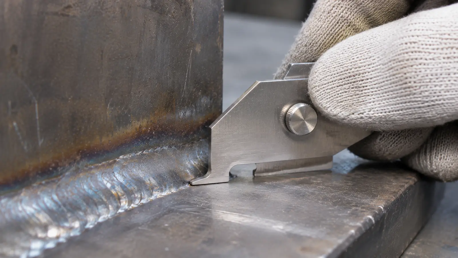
That difference matters. A small shape change does not have the same risk in every product. A decorative cover and a load-bearing support may use different acceptance rules. Inspectors need the approved drawing and relevant code, not only a photograph.
Three questions help place a flaw in context. First, is it at the surface or inside the joint? Second, does it change the metal connection, the weld shape, or the dimensions of the whole part? Third, what does the finished part need to do?
For example, a welded steel cabinet may need flat mounting faces so its doors close well. A narrow weld can still be sound but pull the cabinet out of square as it cools. That is a dimensional problem, not necessarily a missing bond.
Weld flaws can also affect fatigue life, which is how a part holds up under repeated loads. A sharp notch at the edge of a joint may increase local stress. But the presence and size of that notch must be judged against the design and applicable criteria.
What are the most common welding defects?
The fastest way to identify a possible defect is to match the visible sign to the part of the joint that may be affected. The table below is a first-look guide, not a pass-or-fail inspection chart.
| Defect | First clue | Why it matters | Article details |
|---|---|---|---|
| Porosity | Small holes at or inside the bead | Trapped gas; surface may hide internal pores | Porosity details |
| Undercut | Narrow groove beside the weld toe | Local loss of metal; possible stress concentration | Undercut details |
| Spatter | Metal droplets stuck around the bead | Cleanup and finish; check process stability | Spatter details |
| Lack of fusion | Area that failed to bond to base metal or a prior pass | Weak connection may be hidden | Lack of fusion details |
| Distortion | Bowed plate, tilted angle, twisted frame | Finished part may fail dimensional fit | Distortion details |
| Overlap | Rounded lip sitting over base metal | Metal reaches across surface without fusion | Overlap details |
| Burn-through | Hole or melted opening in the joint | Lost material, especially in thin sheet | Burn-through details |
Porosity: small gas pockets in weld metal
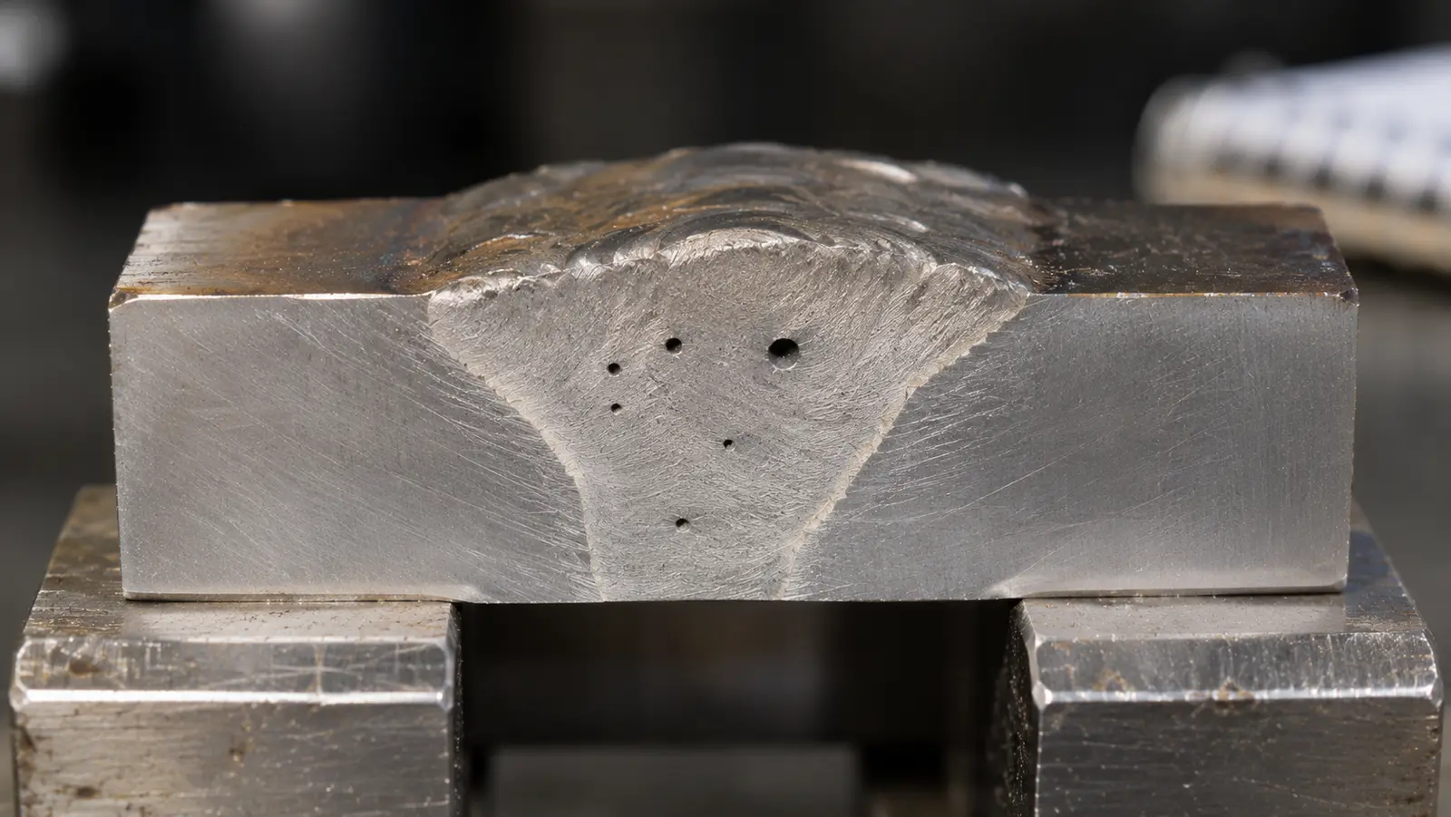
Porosity forms when gas is trapped as molten weld metal becomes solid. The result may be small round holes on the surface or hidden voids inside the bead. A row of pores is not the same issue as a rough surface finish.
Moisture, oil, coatings, or poor shielding can add gas to the weld pool. But the likely cause depends on the welding process and material. A visible pore does not show how much porosity exists below the surface. See the weld porosity guide for gas sources, surface versus internal pores, and prevention choices.
Undercut: a groove beside the weld
Undercut is a groove in the base metal along the edge, or toe, of a weld. It looks as though metal was melted away without enough weld metal filling the space. The groove can act as a stress raiser in a loaded part.
Travel speed, arc conditions, torch angle, and filling technique can all play a role. A shallow groove and a deep one do not have the same result, so appearance alone is not enough. The weld undercut guide covers measurement and code-based review in more detail.
Spatter: droplets outside the weld bead
Spatter consists of small drops of metal thrown from the weld area. They may stick to a panel or leave marks that need cleaning. Spatter is often a finish or cleanup issue, but it should also prompt a check of the process setup.
Its causes may include unstable metal transfer, settings, and shielding conditions. Removing droplets improves appearance but does not fix their cause. The welding spatter guide compares preventing spatter with cleaning it after welding.
Lack of fusion: metal that did not fully join
Lack of fusion means the weld metal did not bond properly with the base metal or with an earlier weld pass. A bead may cover the joint while an unfused area remains beneath it. The surface can look complete even when the connection is not.
Poor joint access, unsuitable settings, contamination, or technique can contribute. Lack of fusion is not identical to incomplete penetration, where the weld does not reach the required depth at the root. The lack of fusion in welding guide explains this distinction and its inspection limits.
Welding distortion: a part that changes shape
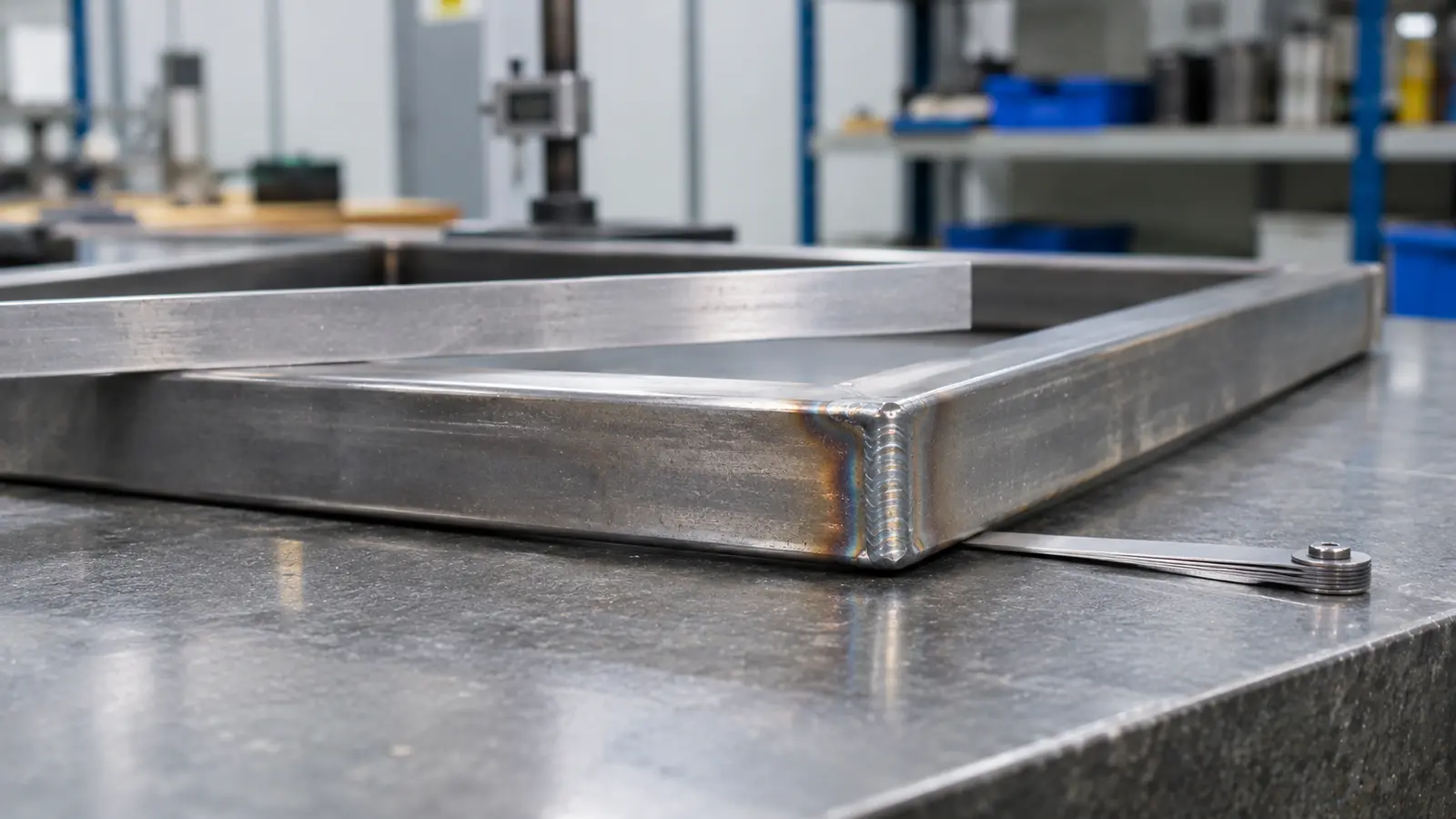
Metal near a weld expands when heated and contracts as it cools. If that movement is uneven, a panel may bow, an angle may open, or a frame may twist. These changes are called welding distortion.
A fixture can hold parts in position, but strong restraint can also leave stress in the joint. Designers must consider material, heat input, weld placement, and welding sequence together. The welding distortion guide compares those controls without turning into a general welding-process selection article.
Overlap: weld metal that rolls onto the surface
Overlap happens when deposited weld metal flows onto nearby base metal without fusing to it. It may look like a rounded lip at the weld toe. This is different from undercut, which removes metal and leaves a groove.
A large or poorly directed weld pool can help create overlap. Its full diagnosis belongs in the weld overlap guide, including a visual comparison with undercut. A normal lap joint is a joint design, not this defect.
Burn-through: a hole made by excess melting
Burn-through is a hole that forms when the weld melts through the material. Thin sheet is especially sensitive because it has less metal to absorb heat and bridge an open gap. An oversized joint gap can make the problem worse.
Reducing heat is not the only possible answer. The team may also need to review part fit, backing, and fixture design. The burn-through welding guide focuses on these thin-metal decisions. Meco's sheet metal basics article explains the material context.
Other flaws: cracks, slag inclusions, and poor penetration
Not every important weld problem fits these seven defect guides. Cracks can form in weld metal or nearby heated material. They may grow under service loads and need prompt expert review rather than a quick appearance-based decision.
Some welding methods can trap slag, a non-metallic residue from the process. Incomplete penetration is another issue: the weld has not reached the required root depth. These flaws may need methods other than visual inspection. Their acceptance depends on the same drawing and code checks used for the main defect group.
What causes welding defects?
Most welding problems come from an interaction between material, joint design, process settings, and the way the work is carried out. The symptom should guide the investigation, but it rarely proves one cause by itself.
Material and surface condition
Oil, moisture, rust, paint, and some coatings can interfere with welding. They may add gas or stop metal from joining as intended. The type of contamination matters: moisture may increase gas-related problems, while a thick oxide layer may block fusion.
Material grade also changes how much heat or preparation is needed. A cleaning plan should match the base metal and any coating. It is not enough to assume that a surface looks clean.
Joint design and part fit
A joint that is too narrow may block access for the welding torch. A gap that is too large can make burn-through more likely on thin sheet. Poor fit can also require extra weld metal, which increases shrinkage as the joint cools.
The drawing should define the joint shape, weld size, needed access, and relevant tolerances. For sheet metal products with several bends and welded joints, Meco's sheet metal assembly guide gives broader production context.
Heat input, travel speed, and weld sequence
Too little effective heat or poor access can leave incomplete fusion. Too much local melting can damage thin sheet. Uneven heating and cooling can change the shape of a larger assembly. These problems cannot all be solved by turning one setting up or down.
Travel speed, current, voltage, joint shape, and the selected method work together. Long seams may also need a balanced welding order to limit movement. The right settings belong to a qualified welding procedure, not a generic online number.
Shielding and consumables
In gas-shielded welding, the molten weld pool needs suitable protection from the air. Problems with gas coverage, drafts, lines, or flow can contribute to porosity. Filler condition and storage can matter as well.
For the process and service context, see Meco's gas-shielded welding services. That page explains the capability, while the porosity cluster is intended to cover defect diagnosis.
How can you recognize a defect before choosing a test?
Begin with the sign you can observe, then decide what that sign cannot tell you. A clean-looking bead does not prove that the weld is fully fused. A rough bead does not, by itself, prove that the joint must be rejected.
| Observed sign | What it could mean | Useful next check |
|---|---|---|
| Small visible pores | Gas may be trapped in weld metal | Note location and pattern; assess need for internal examination |
| Groove at bead edge | Undercut may have left a notch | Measure geometry and compare with joint acceptance criteria |
| Metal lip at bead edge | Possible overlap without fusion | Check profile; determine whether fusion is in question |
| Part twists or bows after welding | Heat-related distortion | Measure flatness, angle, and assembly fit against drawing |
| Bead looks smooth, but joint is critical | Hidden flaws may still exist | Use the inspection plan; do not approve by appearance alone |
A useful first record includes the part number, weld location, material, photograph, drawing revision, and the size of any visible indication. If a flaw repeats along several joints, record where the pattern appears. That detail can help separate a local fit problem from a process-wide issue.
Consider a hypothetical welded cabinet frame. If its corner rises after cooling, inspect overall flatness and squareness. If instead the toe has a narrow groove, measure the groove and check the weld acceptance requirements. The two problems need different evidence, even if they appeared on the same part.
How are welding defects inspected and verified?
Visual inspection is the starting point for many welds, but it does not reveal every internal flaw. The inspection method must match the suspected defect, the material, the weld geometry, and the applicable acceptance rules.
| Method | What it may find | Main limit |
|---|---|---|
| Visual testing (VT) | Surface shape, cracks, visible pores, profile | Cannot confirm hidden fusion or internal voids |
| Dimensional inspection | Flatness, angle, alignment, fit | Does not show internal weld soundness |
| Liquid penetrant (PT) | Surface-breaking indications in suitable nonporous materials | No buried-flaw detection; surface prep matters |
| Magnetic particle (MT) | Surface or near-surface flaws in ferromagnetic materials | Not suitable for nonmagnetic metals |
| Radiography (RT) | Certain internal voids and inclusions | Sensitivity depends on thickness and flaw orientation |
| Ultrasonics (UT) | Internal indications, including some planar flaws | Requires suitable geometry, procedure, and operator |
Start with visual and dimensional checks
Visual testing, often called VT, looks for visible cracks, undercut, overlap, obvious porosity, profile changes, and surface damage. Good lighting, access, and suitable gauges help the inspector describe what is seen. A ruler or weld gauge can measure some surface features, but not hidden fusion.
Dimensional checks focus on the finished part. Straightedges, squares, gauges, or a coordinate measuring machine (CMM) may be used when the drawing demands tighter control. They answer a different question: does the welded assembly still fit its intended shape?
Use further testing for the flaw you suspect
Liquid penetrant testing, or PT, helps reveal surface-breaking flaws in suitable nonporous materials. Magnetic particle testing, or MT, is used for surface and near-surface indications in ferromagnetic materials such as many carbon steels.
Radiographic testing, or RT, uses radiation imaging to examine some internal changes. Ultrasonic testing, or UT, uses sound waves to look for internal indications. Neither method is a universal guarantee. Joint geometry, material, defect orientation, and the inspection procedure affect what can be found.
For example, the absence of pores on the surface does not rule out internal porosity. Likewise, a shallow-looking weld profile cannot confirm that the sidewalls fused. Where the design requires evidence of internal soundness, the team should specify a suitable examination before release.
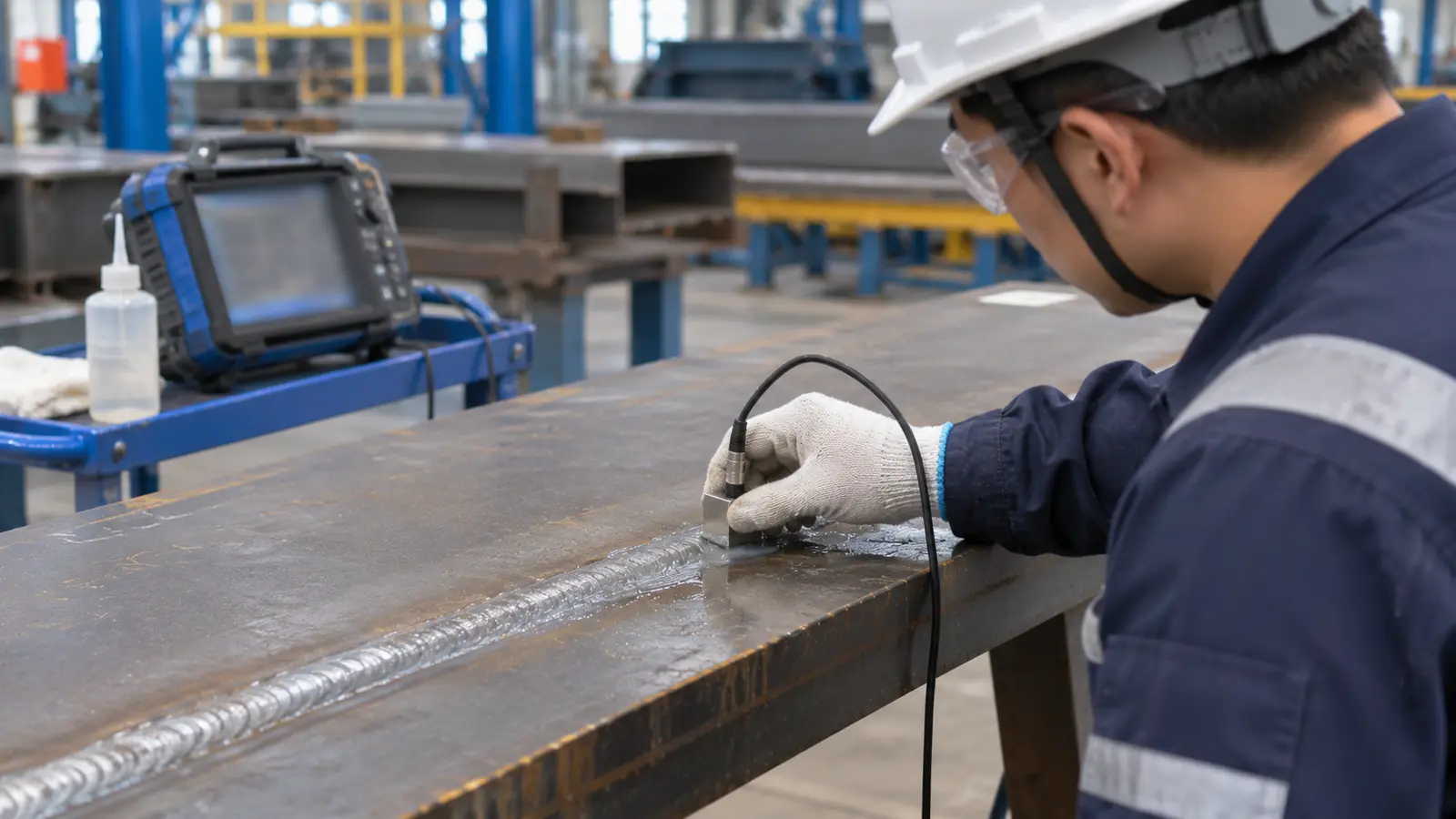
The AWS guidance on nondestructive examination describes how inspection methods differ. A qualified inspector should choose and apply the method required by the job.
Check acceptance against the right requirement
A finding becomes a pass or fail only after it is compared with the correct acceptance criteria. These may come from a customer drawing, a project specification, or an applicable welding code. The limit can vary with joint type, loading, material, and service use.
Do not apply a generic flaw-size limit to every weld. Nor should a shop remove metal from a finished weld simply because it looks uneven. A repair must be reviewed against the approved procedure and the effect it could have on the part.
What should you do when a weld defect is suspected?
Use a short, evidence-based check before making a process change or ordering rework. This prevents a cosmetic issue from being treated as a structural problem, or a hidden risk from being missed.
- Locate and record the sign. Mark the weld, note the material and joint type, and take a clear photograph or inspection record.
- Check the requirement. Read the drawing, weld callout, inspection plan, and applicable acceptance standard before judging the part.
- Choose the right examination. Use visual or dimensional checks first where suitable, then select additional testing if the suspected flaw may be internal.
- Trace likely causes. Review part fit, cleaning, process setup, shielding, and welding sequence. Look for patterns across similar parts.
- Confirm a controlled response. An authorized engineer or quality lead decides whether the part can be accepted, needs further evaluation, or requires repair under an approved procedure.
A key warning: surface grinding can erase a visible indication without removing a deeper problem. It can also reduce weld size. The work should follow a suitable repair plan rather than hiding the evidence.
Reviewing a welded design? Share your drawing, material, joint details, and inspection needs so Meco can discuss manufacturing and quality planning.
Talk to an EngineerHow can manufacturers prevent common welding defects?
The most useful prevention work starts before the arc is struck. Many repeat defects are linked to predictable choices in design, preparation, and control.
Plan the joint for access and fit
Give the torch enough access to reach the joint. Specify realistic root gaps, edge preparation, and alignment needs. If several thin panels must fit together, review tolerances across the assembly, not only on each separate sheet.
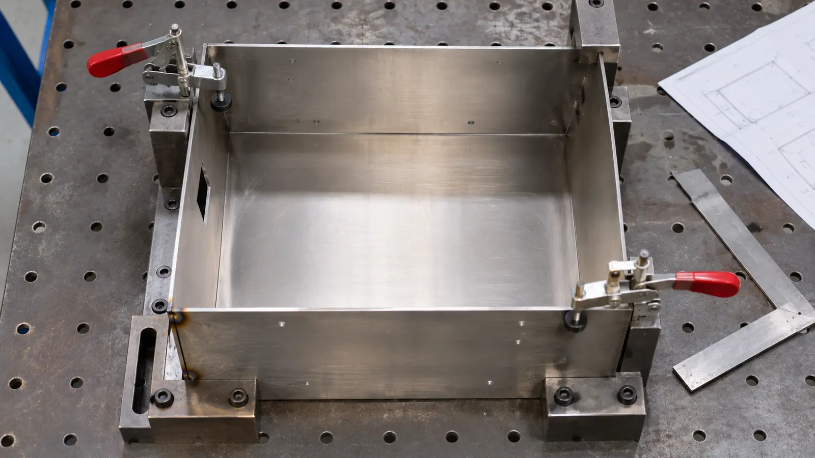
For new products, a design for manufacturing (DFM) review checks whether the part can be built reliably. Meco's R&D engineering support connects drawing review, prototypes, and manufacturing planning.
Use clean parts and a controlled procedure
Material cleaning, consumable handling, and correct shielding reduce avoidable sources of contamination. A welding procedure specification, or WPS, records approved process variables and preparation rules for the work. It is more reliable than making unrelated setting changes between parts.
The people, equipment, and fixtures must be able to repeat the planned method. If the weld bead moves between joints, first check fit and setup stability as well as operator technique.
Limit unnecessary heat and movement
Avoid oversized welds that add metal without a design need. Consider weld placement, balanced sequences, and fixtures when heat could pull the assembly out of shape. Strong clamping is not always better: restraint can also raise locked-in stresses, so the plan must suit the material and part.
A large steel support and a thin stainless enclosure require different controls. In each case, verify fit after cooling rather than assuming the fixture held every feature within tolerance. Process details are covered more deeply in the distortion cluster.
Inspect early enough to stop repeat scrap
Inspect initial parts before committing to a full batch. If a flaw shows up, connect the inspection record to the part, setup, and drawing revision. This makes the next corrective action easier to confirm.
Meco's broader fabrication and welding capabilities cover production planning and welding services. The defect guides focus on why a specific problem forms and how to investigate it.
What information helps plan a reliable welded part?
A useful manufacturing request explains the finished part, not just the welding method. An engineer needs to understand shape, use, materials, and acceptance requirements before selecting checks or process controls.
A practical request includes a 2D drawing or 3D CAD model, base material and thickness, joint details, expected volume, key dimensions, surface finish, and any required inspection or documentation. If a concern already exists, include close photos and the location of the indication.
For example, an enclosure with a flat gasket face may be more sensitive to distortion than a general support bracket. A structural frame may place more weight on fusion and crack-related criteria. Neither should be judged by bead appearance alone.
Meco operates an IATF 16949:2016 certified quality system and offers manufacturing support from engineering review through fabrication and assembly. The relevant welding code and inspection plan still need to be agreed for each project. The certification does not replace a job-specific weld acceptance decision.
Plan a More Reliable Welded Part
Share your drawing, material, joint details, quantity, and inspection needs. Meco can review manufacturability and quality considerations for a planned welded assembly.
- Drawing and material. 2D or 3D files, grade, thickness
- Joint requirements. fit, weld size, access
- Quality needs. tolerances, testing, documentation
- Production plan. prototype or expected batch size
References and sources
- American Welding Society (AWS), B1 Committee, Guide for the Nondestructive Examination of Welds and Guide for the Visual Examination of Welds
- TWI, Porosity in Welding: Defects / Imperfections in Welds
- TWI, Weld Defects: Lack of Sidewall and Inter-Run Fusion
- TWI, A General Review of Geometric Shape Imperfections: Types and Causes, Part 1
- TWI, Distortion: Prevention by Design
