
Welding joins two or more pieces of metal by applying heat, pressure, or both until they fuse into a single, permanent connection. It is the backbone of modern manufacturing — from car frames and pressure vessels to aircraft fuselages and EV battery enclosures. But not every weld is the same. There are dozens of types of welding, each designed for different materials, thicknesses, speeds, and quality requirements.
If you source welded parts or assemblies for automotive, aerospace, electronics, or heavy equipment, picking the wrong process costs you time, money, and quality. This guide covers every major welding type used in North American industrial manufacturing in 2026. We explain how each process works, when to use it, and how to choose the right one. We wrote it for engineers, sourcing managers, and product designers who buy welded parts — not for hobbyists shopping for a home welder.
Quick Answer — What Are the Main Types of Welding?
The most common welding processes in manufacturing are MIG (GMAW), TIG (GTAW), Stick (SMAW), Flux-Cored (FCAW), Laser, Resistance (Spot/Seam), Submerged Arc (SAW), Plasma Arc (PAW), Electron Beam (EBW), Ultrasonic, and Friction Stir (FSW). Each differs in heat source, shielding method, speed, precision, and cost. The right choice depends on your material, thickness, production volume, and quality requirements.
What Is Welding?
Welding is a fabrication process that permanently joins materials — usually metals or thermoplastics — by melting the edges of the workpieces together, often with a filler material added to strengthen the joint. As the molten pool cools and solidifies, it forms a bond that is typically as strong as or stronger than the base material.
The international standard ISO 4063:2023 classifies over 100 welding, brazing, soldering, and cutting processes by reference number. In everyday manufacturing, engineers work with about 10 to 15 core methods. The sections below cover each one in detail.
The Welding Industry in 2026: Key Numbers
Before diving into individual processes, here is a snapshot of the welding industry that affects process selection, labor availability, and lead times across North America.
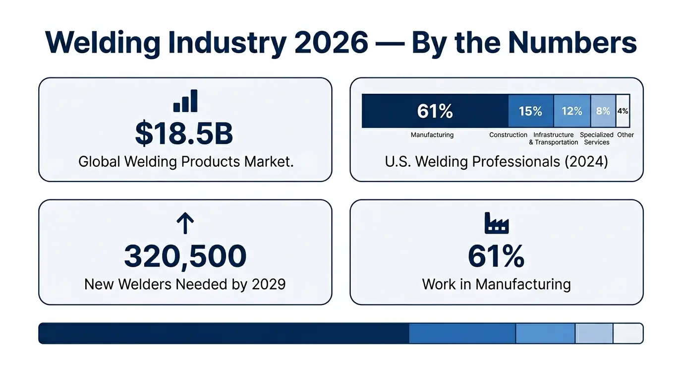
The American Welding Society (AWS) estimated the U.S. welding workforce at 771,000 professionals in 2024. Over 157,000 are nearing retirement. The AWS projects 320,500 new welding professionals will be needed by 2029 just to meet demand. That shortage is one reason many OEMs are turning to automated welding — robotic MIG, laser, and resistance welding cells — to maintain throughput.
The global welding products market is valued at approximately $18.5 billion in 2026, growing at a 6.9% CAGR through 2035, per The Business Research Company. The fastest-growing segments are laser welding equipment (driven by EV battery manufacturing) and robotic arc welding systems (driven by labor constraints).
The Major Types of Welding Processes
Below is a complete breakdown of every major welding process used in modern manufacturing. We group them into arc welding methods, high-energy beam methods, resistance methods, and solid-state/specialty methods.
MIG Welding (GMAW — Gas Metal Arc Welding)
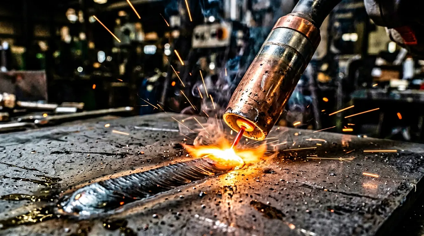
MIG welding is the workhorse of industrial manufacturing. A continuously fed consumable wire electrode creates an arc between the wire and the workpiece. A shielding gas — usually argon, CO₂, or a mix — protects the molten weld pool from atmospheric contamination.
MIG is fast. It offers high deposition rates, which means more filler metal is laid down per minute than with most other arc processes. It works well on mild steel, stainless steel, and aluminum in gauges from about 0.6 mm up to 13 mm and beyond. It is the easiest arc process for beginners to learn because the wire feeds automatically — the operator only needs to manage travel speed, gun angle, and distance.
The main limitations are that MIG welds can require post-weld cleanup (spatter, grinding) for cosmetic applications, and the process does not perform well outdoors. Wind disperses the shielding gas, which causes porosity. For outdoor work, flux-cored welding is a better choice. Meco operates robotic and manual gas shielded welding (MIG/GMAW and TIG/GTAW) lines for medium-to-high volume production.
TIG Welding (GTAW — Gas Tungsten Arc Welding)
TIG welding uses a non-consumable tungsten electrode to create the arc. The welder feeds a separate filler rod into the weld pool by hand while an inert shielding gas — typically pure argon — protects the joint. A foot pedal controls the amperage in real time, giving the operator precise heat control.
TIG produces the cleanest, most precise welds of any common arc process. The bead is smooth, spatter-free, and often requires no post-weld grinding. It is the standard for thin-gauge stainless steel (under 3 mm), aluminum, titanium, copper, and exotic alloys. Industries that demand cosmetic or critical welds — aerospace, medical devices, food equipment, and architectural metalwork — rely heavily on TIG.
The tradeoffs are speed and cost. TIG is significantly slower than MIG, and the skill required is higher. A TIG welder needs excellent hand coordination and a thorough understanding of heat input. For production environments, Meco's dedicated TIG welding cells combine manual precision with robotic consistency to balance quality and throughput.
Stick Welding (SMAW — Shielded Metal Arc Welding)
Stick welding is the oldest and most portable arc process still in wide use. A flux-coated consumable electrode (the "stick") creates an arc with the workpiece. As the electrode melts, the flux coating generates a shielding gas and a layer of slag that protects the weld pool.
Stick welding requires minimal equipment — just a power source, an electrode holder, a ground clamp, and electrodes. It works outdoors, in wind, in rain, and on dirty or rusty metal. That makes it the default choice for construction sites, pipeline work, field repairs, and structural steel erection. It handles a wide range of metals including carbon steel, stainless steel, and cast iron.
The downsides are lower deposition rates (the welder must stop and replace each electrode as it is consumed), heavy slag that must be chipped and wire-brushed after every pass, and a higher skill requirement than MIG. Stick welding is rarely used in high-volume manufacturing because it is too slow, but it remains essential for maintenance, repair, and field work.
Flux-Cored Arc Welding (FCAW)
Flux-cored welding is similar to MIG — it uses a continuously fed wire electrode. The difference is that the wire is tubular and filled with flux. The flux generates its own shielding gas as it burns, so FCAW can run with or without an external gas supply.
Self-shielded FCAW (no gas) works well outdoors and in windy conditions — a major advantage over MIG. Gas-shielded FCAW (with external gas) provides cleaner welds and is used indoors for structural steel and heavy fabrication. FCAW offers higher deposition rates than Stick and approaches MIG speed on thick materials. It is common in shipbuilding, structural steel, pipeline welding, and heavy equipment manufacturing.
The main limitations are slag (which must be removed between passes) and higher fume generation compared to MIG. FCAW wire is also more expensive per pound than solid MIG wire.
Submerged Arc Welding (SAW)
Submerged arc welding feeds a consumable wire electrode beneath a blanket of granular flux. The arc burns entirely beneath the flux layer — no visible arc, no spatter, and virtually no fumes. The flux melts to form a protective slag that peels away easily after cooling.
SAW is an automated or semi-automated process designed for long, straight, or circumferential welds on thick materials. It delivers extremely high deposition rates — 4 to 10 times faster than Stick welding — and deep penetration. Thermal efficiency is around 60%, compared to about 25% for Stick. SAW is standard in pressure vessel fabrication, shipbuilding, wind tower manufacturing, and structural beam production. It is not practical for short welds, tight spaces, or vertical/overhead positions because the granular flux relies on gravity.
Plasma Arc Welding (PAW)
Plasma arc welding is closely related to TIG. Both use a non-consumable tungsten electrode and inert shielding gas. The difference is that PAW constricts the arc through a small copper nozzle, creating a much hotter, more focused plasma jet. Temperatures can exceed 28,000 °C.
The constricted arc gives PAW higher energy density, deeper penetration, and a narrower heat-affected zone than TIG. PAW operates in three modes: micro-plasma (for materials as thin as 0.025 mm), melt-in mode (similar to TIG but faster), and keyhole mode (for single-pass full-penetration welds on plate up to about 10 mm). It is used in aerospace engine components, medical equipment, coated steels, and electronics.
The primary limitation is equipment cost. PAW torches, power sources, and control systems are more expensive than TIG. Operator training requirements are also higher.
Laser Welding (LBW)
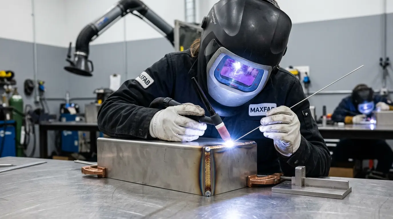
Laser welding uses a focused beam of coherent light to melt and fuse metals. The beam can be generated by a fiber laser, CO₂ laser, or Nd:YAG laser. Fiber lasers dominate modern manufacturing due to their efficiency, beam quality, and low maintenance.
Laser welding produces deep, narrow welds with a minimal heat-affected zone (HAZ). That translates to very low thermal distortion — critical for thin sheet metal assemblies and parts with tight flatness tolerances. The process is extremely fast and highly automatable, making it ideal for high-volume production. It is the method of choice for EV battery module assembly, precision electronics, and thin-gauge automotive components.
The main barriers are high equipment cost and the need for very tight joint fit-up (the focused beam is narrow and does not bridge gaps well). Meco operates dedicated laser welding cells integrated with robotic handling for automotive and electronics programs.
Resistance Welding (Spot, Seam, and Projection)
Resistance welding joins overlapping metal sheets by passing a high electrical current through them while clamping them between copper electrodes. The electrical resistance at the joint interface generates enough heat to form a fused nugget — all in a fraction of a second.
Spot welding (RSW) is the most common variant. Two pointed electrodes squeeze the sheets together and fire a pulse of current, creating a single weld "spot." Seam welding uses wheel-shaped electrodes that roll along the joint to create a continuous, leak-tight seam. Projection welding concentrates the current at raised points stamped into one part.
Resistance welding is extremely fast (sub-second per spot), highly repeatable, easily automated, and requires no filler material or shielding gas. It is the dominant joining method in automotive body-in-white assembly — a single car body can contain 3,000 to 5,000 spot welds. Meco's resistance welding capabilities include automated spot, projection, and seam welding for medium-to-high volume programs.
Electron Beam Welding (EBW)
Electron beam welding uses a focused beam of high-velocity electrons to generate intense heat at the joint. The process takes place in a vacuum chamber to prevent the beam from scattering. EBW produces extremely deep, narrow welds — depth-to-width ratios of 25:1 are possible — with a tiny heat-affected zone.
EBW is used for critical aerospace and defense components, nuclear reactor parts, and high-precision medical implants where weld quality and structural integrity are paramount. It can weld materials that are difficult to join by other methods, including refractory metals and dissimilar metal combinations. The limitations are high equipment cost, the need for a vacuum environment (which restricts part size), and slower cycle times.
Ultrasonic Welding (USW)
Ultrasonic welding uses high-frequency mechanical vibrations (typically 20–40 kHz) to create a solid-state bond between parts. The parts are clamped together under pressure, and the ultrasonic vibrations generate friction at the interface. This friction produces localized heat that softens the material just enough to bond — but well below the melting point.
Ultrasonic welding is the standard for joining thermoplastics (polyethylene, polypropylene, ABS, nylon) and thin metal foils (copper, aluminum, nickel). It is fast (cycle times under one second), clean (no fumes, filler, or flux), and highly automatable. Applications include automotive wire harnesses, battery tab connections, medical device filters, sensor housings, and consumer product packaging.
Friction Stir Welding (FSW)
Friction stir welding generates heat through a rotating non-consumable tool that plunges into the joint line and "stirs" the softened material together. It is a solid-state process — the metal never fully melts, which eliminates porosity, solidification cracking, and other fusion-weld defects.
FSW is especially important in aerospace and EV manufacturing for joining large aluminum panels. The joints are defect-free and retain near-parent-metal strength. Boeing uses FSW for rocket fuel tank panels, and many EV manufacturers use it for battery tray closures. The limitation is that the parts must be rigidly clamped, and the process is best suited for linear or circumferential joints.
MIG vs. TIG Welding: Head-to-Head Comparison
MIG and TIG are the two most frequently compared welding processes. The table below summarizes their key differences for sourcing managers and engineers choosing between them.
| Factor | MIG (GMAW) | TIG (GTAW) |
|---|---|---|
| Arc / heat source | Consumable wire electrode + shielding gas | Non-consumable tungsten + separate filler rod |
| Speed | Fast — high deposition rate | Slow — manual filler feed |
| Precision | Good | Excellent — best for thin material |
| Weld appearance | Good; may need grinding for cosmetic finish | Excellent; clean, smooth bead, often no cleanup |
| Material thickness | Medium to thick (1 mm – 25 mm+) | Thin to medium (0.5 mm – 6 mm typical) |
| Skill level | Beginner-friendly | Advanced — two-hand coordination + foot pedal |
| Cost per weld | Low | High (slower cycle time, higher labor) |
| Heat-affected zone | Larger — more distortion risk | Smaller — less distortion |
| Automation | Excellent — easy to robotize | Good — robotic TIG common for precision work |
| Best applications | Structural steel, auto frames, production welding | Aerospace, medical, food equipment, thin stainless/aluminum |
For a deeper comparison — including material-specific guidance and process selection support — see Meco's gas shielded welding services page.
Types of Welding Joints
A welding joint is the configuration of the workpieces where they are joined. There are five basic joint types. The right joint depends on geometry, load requirements, and torch access.
| Joint Type | Configuration | Strength | Common Uses |
|---|---|---|---|
| Butt joint | Two pieces aligned edge-to-edge in the same plane | Highest (with full penetration) | Pipe welding, plate fabrication, pressure vessels |
| Lap joint | Two overlapping pieces, one on top of the other | Good (fillet or spot weld) | Sheet metal assembly, automotive panels, spot-welded enclosures |
| Tee joint | One piece perpendicular to another, forming a "T" | Good (fillet weld both sides) | Structural frames, brackets, stiffeners |
| Corner joint | Two pieces meeting at a right angle at their edges | Moderate to good | Box frames, enclosures, housings |
| Edge joint | Two pieces side-by-side with edges aligned | Low to moderate | Sheet metal flanges, thin panels, low-load applications |
Joint design affects weld quality, access, inspection, and cost. A butt joint with full penetration is the strongest configuration but requires more preparation and filler material. Your design engineer should choose the joint that meets the structural requirement at the lowest cost — and your manufacturer should flag joint design issues during DFM review.
What Is Tack Welding?
Tack welding is not a separate process. It is a technique used within any arc welding method. A tack weld is a short, temporary weld (typically 10–25 mm long) used to hold parts in position before the final weld is made. Think of it as a metal clamp that keeps everything aligned.
Tack welds must be strong enough to resist thermal stresses during final welding but small enough to be fully consumed into the final bead. Poor tack welding — welds that are too large, placed incorrectly, or contain defects — is a common root cause of fit-up problems and weld defects in production. Proper spacing, size, and placement of tack welds should be specified in the welding procedure.
Common Welding Defects and How to Prevent Them
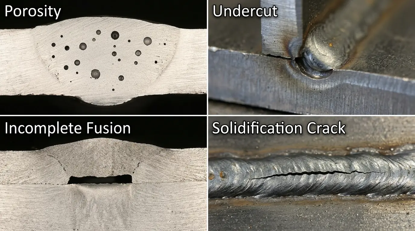
Even the best welding process produces defective joints if process parameters, materials, or technique are off. The table below covers the most common defects, their causes, and prevention. For a detailed visual guide, ESAB's welding defect reference is an excellent resource.
| Defect | Description | Common Causes | Prevention |
|---|---|---|---|
| Porosity | Gas pockets trapped in solidified weld metal | Contaminated base metal, moisture, insufficient shielding gas | Clean surfaces, check gas flow, use dry electrodes |
| Undercut | Groove melted into base metal along the weld edge, not filled | Excessive travel speed, too-high amperage, wrong torch angle | Reduce heat input, slow travel speed, adjust angle |
| Incomplete fusion | Weld metal does not fully bond to base metal or previous pass | Low heat input, fast travel, improper joint preparation | Increase amperage, slow down, ensure proper fit-up |
| Cracking | Fractures in the weld or heat-affected zone | High residual stress, hydrogen contamination, rapid cooling | Preheat, use low-hydrogen electrodes, control cooling |
| Spatter | Droplets of molten metal scattered around the weld | High wire-feed speed, wrong voltage, contaminated wire | Optimize voltage/wire speed, anti-spatter spray, clean wire |
| Distortion | Warping from uneven thermal expansion | Excessive heat input, wrong sequence, poor fixturing | Balanced welding sequence, intermittent welding, proper fixtures |
Quality at Meco
Every welded assembly at Meco passes through in-process and final inspection — including visual inspection per AWS D1.1 criteria, dimensional verification, and destructive/non-destructive testing (UT, PT, X-ray) where required. Our IATF 16949:2016 quality system ensures defects are caught and corrected before parts ship.
What Is Weldability?
Weldability describes how easily a material can be welded to produce a sound, defect-free joint under production conditions. High-weldability materials (like mild steel, 304 stainless, and 6061 aluminum) tolerate a wide range of process parameters and rarely crack. Low-weldability materials (like high-carbon steel, cast iron, and some titanium alloys) require preheat, post-weld heat treatment, or special filler metals.
The single most important indicator for steel weldability is the carbon equivalent (CE). Steels with a CE below 0.40 are generally easy to weld. Steels with a CE above 0.60 require preheat and careful process control. When specifying a material for a welded assembly, always confirm weldability with your manufacturing partner before finalizing the design. Meco's engineering team reviews material-to-process compatibility as part of every DFM analysis.
The M‑A‑T‑C‑H Framework: How to Choose the Right Welding Process
Choosing the right welding process is one of the most important decisions in any fabrication project. We use a five-factor framework called M‑A‑T‑C‑H to help OEM customers make the right call every time.
M‑A‑T‑C‑H Decision Framework
M — Material: What metal (or plastic) are you joining? Each material has different thermal properties and weldability.
A — Application: What is the joint's function? Structural load, pressure containment, cosmetic appearance, or electrical conductivity?
T — Throughput: How many parts per hour/day/month? Low volume favors manual TIG; high volume favors MIG, laser, or resistance.
C — Cost: What is your total cost target per joint — including labor, consumables, equipment, and post-weld finishing?
H — Heat Sensitivity: Can the part tolerate thermal distortion? Thin sheet metal and tight-tolerance assemblies need low-HAZ processes (laser, TIG, resistance).
Worked Example: You are sourcing a stainless steel (304) medical device enclosure from 1.5 mm sheet metal. Apply M‑A‑T‑C‑H: Material = 304 stainless, weldable but heat-sensitive at thin gauge. Application = cosmetic enclosure, must be smooth with no visible spatter. Throughput = 500 units/month. Cost = moderate; can justify quality over speed. Heat sensitivity = high — distortion on 1.5 mm must be minimal. The answer: TIG welding for prototyping and low volume, transitioning to laser welding if volume increases. MIG would be too hot and too messy for this application.
| Primary Factor | Best Process | Why |
|---|---|---|
| Thin material + cosmetic finish | TIG or Laser | Precise heat control, clean bead, minimal distortion |
| High volume + sheet metal overlap | Resistance (Spot) | Sub-second cycle, no consumables, easily automated |
| Structural steel + speed | MIG or FCAW | High deposition rate, strong joints, excellent automation |
| Outdoor / field work | Stick or self-shielded FCAW | No shielding gas tanks needed, wind-tolerant |
| Thermoplastics or thin foils | Ultrasonic | Solid-state bond, no heat damage, sub-second cycle |
| Deep penetration, critical joint | Electron Beam or SAW | Very high energy density, narrow HAZ, strongest joints |
| Dissimilar metals or aluminum panels | Friction Stir | Solid-state, no melting, no porosity, near-parent strength |
Welding Process Quick-Reference Table
Use this table as a side-by-side comparison of all major welding processes covered in this guide.
| Process | Abbreviation | Speed | Precision | Best Materials | Automation | Cost |
|---|---|---|---|---|---|---|
| MIG | GMAW | Fast | Good | Steel, aluminum, stainless | Excellent | Low |
| TIG | GTAW | Slow | Excellent | All metals, esp. thin gauge | Good | High |
| Stick | SMAW | Slow | Fair | Steel, stainless, cast iron | Poor | Low |
| Flux-Cored | FCAW | Fast | Good | Steel, stainless, nickel alloys | Good | Medium |
| Submerged Arc | SAW | Very fast | Good | Carbon steel, low-alloy steel | Excellent | Low (at volume) |
| Plasma Arc | PAW | Medium | Excellent | Stainless, titanium, nickel | Good | High |
| Laser | LBW | Very fast | Excellent | Steel, aluminum, thin gauge | Excellent | Medium–High |
| Resistance (Spot) | RSW | Very fast | Good | Steel, aluminum sheet | Excellent | Very low |
| Electron Beam | EBW | Medium | Excellent | Refractory metals, superalloys | Good | Very high |
| Ultrasonic | USW | Very fast | Good | Thermoplastics, thin metal foils | Excellent | Low |
| Friction Stir | FSW | Medium | Excellent | Aluminum, copper, soft alloys | Excellent | High |
How Welding Fits into Turnkey Manufacturing
Welding is rarely a standalone service. In turnkey manufacturing, welded joints are one step in a multi-process workflow that typically includes laser cutting or stamping of blanks, CNC bending or forming, welding, CNC machining of post-weld features (tapped holes, mating surfaces), surface finishing (powder coating, plating, anodizing), and final mechanical assembly.
When all of these processes happen under one roof, tolerances are tighter, lead times are shorter, and quality handoff gaps disappear. A welded bracket that needs post-weld machining and powder coating can ship in one delivery from one partner — instead of bouncing between three vendors with three quality systems and three lead time commitments.
That single-source model is what Meco delivers. With 40+ manufacturing processes, IATF 16949:2016 certified facilities, and production capacity in Thailand and China backed by U.S. engineering support, we handle the full sequence from flat sheet to finished, inspected, packaged assembly. No minimum order quantities. Quote in under 24 hours.
Frequently Asked Questions About Types of Welding
How many types of welding are there?
ISO 4063:2023 classifies over 100 welding, brazing, and cutting processes by reference number. In everyday manufacturing, engineers work with about 10 to 15 core methods. The most common are MIG (GMAW), TIG (GTAW), Stick (SMAW), Flux-Cored (FCAW), Laser, Resistance (Spot), Submerged Arc (SAW), Plasma Arc (PAW), Electron Beam, and Ultrasonic welding.
What are the 4 main types of welding?
The four most common welding processes are MIG (Gas Metal Arc Welding), TIG (Gas Tungsten Arc Welding), Stick (Shielded Metal Arc Welding), and Flux-Cored Arc Welding. Together, these four methods handle the majority of industrial and structural welding work across North America.
What is the strongest type of welding?
No single welding type is universally strongest. Weld strength depends on the material, joint design, filler metal, and operator skill. TIG welding typically produces the strongest, most consistent welds on thin materials. MIG and Stick produce comparable strength on structural steel when performed by a qualified welder. Electron beam welding achieves extremely high-strength joints in aerospace applications due to deep penetration and a narrow heat-affected zone.
Which is easier to learn — MIG or TIG?
MIG welding is easier to learn. The wire feeds continuously, so beginners can focus on travel speed and gun angle. TIG welding requires both hands — one feeds the filler rod, the other controls the torch — plus a foot pedal for amperage. Most welding schools start students on MIG before moving to TIG.
What type of welding is best for sheet metal?
TIG welding is the best choice for thin sheet metal (under 3 mm) because it gives the welder precise heat control and produces clean, low-distortion welds. For high-volume sheet metal production, resistance spot welding and laser welding are faster and more cost-effective. MIG welding works well on medium-gauge sheet metal when speed matters more than appearance.
Is MIG or TIG welding stronger?
When both welds are performed correctly by a qualified welder, MIG and TIG produce joints of comparable strength. TIG welds tend to have fewer defects and a smaller heat-affected zone, which gives them an edge in fatigue-critical applications. MIG welds provide higher deposition rates, making them more practical for structural steel where volume and speed matter.
What causes undercut in welding?
Undercut is a groove melted into the base metal along the edge of a weld that is not filled by weld metal. Common causes include excessive travel speed, too-high amperage, incorrect electrode angle, and improper weave technique. Prevention involves reducing heat input, slowing travel speed, and adjusting the torch angle to direct the arc into the joint properly.
What is ultrasonic welding used for?
Ultrasonic welding uses high-frequency vibrations (typically 20–40 kHz) to join thermoplastics or thin metal foils without heat from an external source. It is widely used in automotive (wire harnesses, interior trim), medical devices (filters, tubing connections), electronics (battery tabs, sensor housings), and consumer packaging. It produces clean, fast joints with no consumables.
Which welding joint is the strongest?
A properly executed butt joint with full penetration is generally the strongest because the weld metal fuses through the entire thickness of both workpieces. However, joint strength also depends on weld quality, filler metal selection, and base material properties. Lap joints and tee joints can approach butt-joint strength when designed with adequate fillet size.
Can you weld plastic?
Yes. Thermoplastics such as polyethylene, polypropylene, PVC, and ABS can be welded using hot-gas welding, ultrasonic welding, laser welding, vibration welding, or spin welding. Each method softens the plastic at the joint interface so the molecules intermingle and bond as they cool. Thermoset plastics (epoxies, phenolics) cannot be welded because they do not re-melt once cured.
Need Expert Welding for Your Next Manufacturing Project?
Choosing the right welding process is where design intent meets manufacturing reality. Get it wrong and you pay for rework, missed deadlines, and failed quality audits. Meco bridges that gap with DFM-driven engineering review on every project, backed by IATF 16949:2016 certified quality and in-process weld inspection at every stage.
With 30+ years of turnkey manufacturing experience and 40+ in-house processes, we handle everything from cutting and forming to welding, machining, finishing, assembly, and global delivery — under one accountable partner.
- Full Welding Capability: TIG, MIG, laser, resistance (spot/seam/projection), and robotic welding — all in-house.
- 40+ Manufacturing Processes: CNC machining, die casting, stamping, injection molding, surface finishing, and mechanical assembly under one roof.
- IATF 16949:2016 Certified: Automotive-grade quality applied across every industry. 99.8% on-time delivery.
- DFM Feedback with Every Quote: Our engineering team flags joint design issues, weldability concerns, and cost-saving opportunities before production starts. Quotes in under 24 hours.
- Prototype to 10M+ Units: No minimum order quantities. Scale from 10 pieces to 10 million with zero friction.
Send us your drawings and let Meco's engineering team recommend the right welding process for your material, volume, and budget.
Get a Free Welding Quote