Sheet metal assembly is the process of joining two or more fabricated sheet metal components into a functional product or subassembly using methods such as welding, mechanical fastening, riveting, clinching, or adhesive bonding. It is the final production stage where precision cutting, bending, and forming converge into a finished unit that must meet dimensional, structural, and cosmetic requirements.
For OEMs and engineering teams sourcing manufacturing partners, sheet metal assembly is also where supply chain decisions become visible. A bracket that was cut and bent to spec can still fail at assembly if tolerances stack up, joining methods are poorly selected, or upstream processes were managed by disconnected suppliers. According to Precedence Research, the global sheet metal market reached an estimated USD 354 billion in 2025 and is projected to grow at a 5.0% CAGR through 2035, which makes getting assembly right a competitive advantage, not an afterthought.
This guide covers everything engineers and sourcing managers need to know: the complete manufacturing process from flat sheet to assembled product, every major joining technique with pros, cons, and best-fit applications, tolerance standards and stack-up principles, materials selection, DFM rules, and how to evaluate a manufacturing partner. Whether you are designing an electronics enclosure, scaling an automotive subassembly, or consolidating sheet metal vendors, this is the reference you will keep coming back to.
What Is Sheet Metal Assembly?
Sheet metal assembly is the engineering process of combining individually fabricated sheet metal parts into a single functional unit. It follows upstream operations such as laser cutting, punching, CNC bending, stamping, and forming, and it determines whether those individually accurate parts come together into a product that fits, functions, and lasts.
Unlike machining or casting, where a single workpiece is shaped to final geometry, sheet metal assembly involves the alignment and joining of multiple flat-pattern or formed components. That makes it uniquely sensitive to cumulative dimensional variation. Two parts, each within spec, can produce an out-of-tolerance assembly if their individual deviations compound in the same direction. This phenomenon, called tolerance stack-up, is the single biggest quality risk in sheet metal assembly and the reason why the process demands careful planning from the design stage.
Sheet metal assemblies appear across virtually every manufacturing sector. Examples range from welded chassis frames in heavy equipment to riveted aircraft panels, fastened electronics enclosures, clinched HVAC ductwork, and powder-coated control cabinets for industrial automation. What unites them is a shared need for repeatability, structural integrity, and a joining method matched to the application.
Manufacturing Process Steps: From Flat Sheet to Finished Assembly
Understanding the full manufacturing sequence is essential for anyone sourcing sheet metal assemblies, because assembly quality depends on every step that comes before it. A late-stage assembly defect is rarely caused by the joining operation alone. It is typically the result of a material issue, a cutting inaccuracy, a bend deviation, or a surface-preparation shortcut that went undetected upstream. The following process steps represent the standard production flow for sheet metal parts and assemblies.
Step 1: Material Selection and Preparation
Every sheet metal project begins with choosing the right base material. The most common substrates include mild steel (low cost, high strength, weldable), stainless steel (corrosion resistant, hygienic, durable), aluminum (lightweight, thermally conductive, corrosion resistant), brass and copper (electrically conductive, machinable), and galvanized steel (pre-coated corrosion resistance). Material selection affects every downstream decision: which cutting process can handle the gauge and alloy, what bend radius is achievable without cracking, which joining methods are compatible, and what surface finish is required. For a complete breakdown of materials by process, Meco publishes detailed compatibility data across its surface finishing and fabrication capability pages.
Step 2: Cutting
Flat sheet stock is cut into individual blanks or finished flat patterns using one or more cutting methods. Laser cutting is the most versatile, capable of processing steel up to 25 mm with tight dimensional accuracy (typically +/-0.1 mm) and excellent edge quality. Punching and turret pressing are faster for high-volume production of parts with standard hole patterns. Shearing provides straight-line cuts on thinner gauges at high speed. Plasma and waterjet cutting handle thicker materials or heat-sensitive substrates. Custom laser cutting services are particularly well suited to prototyping and low-to-medium volume production because they require no hard tooling and support rapid design iteration.
Step 3: Forming and Bending
Flat blanks are formed into three-dimensional shapes on CNC press brakes, roll-forming machines, or stamping presses. CNC bending is the most common forming operation for sheet metal assemblies because it converts 2D flat patterns into brackets, channels, enclosures, and structural sections with repeatable accuracy. Typical press brake bending tolerances are +/-0.5 degrees on bend angle and +/-0.1 to 0.2 mm on linear dimensions for standard gauges, as documented in industry references such as The Fabricator's tolerance guide. More aggressive tolerances are achievable but require tighter process control, higher-quality tooling, and more frequent in-process inspection. Metal stamping and progressive stamping serve higher volumes where tooling investment is justified by per-part cost savings.
Step 4: Secondary Machining (If Required)
Some sheet metal assemblies require features that cannot be produced by cutting and forming alone. Tapped holes, reamed bores, countersinks, and precision-machined mating surfaces are added using CNC drilling, tapping, or milling. This step bridges sheet metal fabrication and custom CNC machining and is common in assemblies that interface with machined housings, shafts, or bearing seats.
Step 5: Surface Finishing
Before assembly, individual parts typically receive a protective or cosmetic surface treatment. Common finishes for sheet metal include powder coating (durable, available in many colors and textures, applied electrostatically and oven-cured), zinc plating (corrosion protection for steel, per ASTM B633), painting (wet spray for cosmetic and protective applications), e-coating (electrodeposition coating for uniform coverage on complex geometries), anodizing (for aluminum substrates, per MIL-A-8625), and galvanizing (hot-dip zinc coating for heavy-gauge steel, per ASTM A123). Finishing must be planned alongside assembly because coatings add thickness that can affect hole sizes, thread engagement, mating surface fit, and press-fit clearances. Masking critical features before finishing is standard practice. For a complete breakdown of available coatings matched to substrate, see Meco's surface finishing services.
Step 6: Assembly
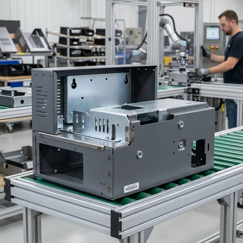
With all components cut, formed, machined (if needed), and finished, the parts move to assembly. This is where joining methods such as welding, riveting, fastening, clinching, or adhesive bonding bring individual pieces together into a working product. The assembly stage also includes hardware insertion (PEM nuts, studs, standoffs), torque-controlled fastening, alignment verification, functional testing, and in-process inspection. A detailed breakdown of every major assembly technique follows in the next section of this guide.
Step 7: Quality Inspection and Documentation
After assembly, finished units undergo final inspection. Depending on the industry and program requirements, this may include CMM dimensional verification, visual inspection to cosmetic standards, torque audits, functional testing, and documentation such as First Article Inspection (FAI) reports, PPAP submissions, material certificates (COA), and full lot traceability records. For programs governed by IATF 16949:2016 or similar quality systems, every step from incoming material through final pack-out is documented and traceable.
Step 8: Packaging and Delivery
The final step is packaging the assembled product for shipment. Custom packaging, labeling, kitting, and palletizing protect parts during transit and ensure they arrive ready for installation or further integration at the customer's facility. For high-volume OEM programs, this step often includes JIT delivery scheduling, safety stock buffering, and distribution through regional warehouses. Meco's warehousing and logistics network spans North America and Asia, with locations in the U.S. (Ohio and Florida), Canada, Japan (Tokyo and Osaka), and Thailand.
Sheet Metal Assembly Techniques: Every Major Joining Method Explained
Choosing the right joining method is the most consequential decision in sheet metal assembly. It determines structural performance, production speed, serviceability, cost per unit, and cosmetic outcome. Below is a complete technical overview of every major technique used in modern sheet metal fabrication and assembly.
Welding
Welding fuses two or more metal parts by applying heat to melt and join the base material, often with a filler rod or wire. It creates permanent, high-strength joints that are frequently as strong as or stronger than the parent metal. Welding is the preferred method when structural integrity, leak-proof sealing, or continuous-seam strength is required. Structural steel welding is governed by AWS D1.1 (Structural Welding Code - Steel), the industry standard for workmanship, qualification, and acceptance criteria.
MIG Welding (GMAW): Uses a continuously fed consumable wire electrode and shielding gas. MIG welding is fast, versatile, and well suited for medium-to-thick gauge steel and aluminum. It is the workhorse method for structural sheet metal assemblies and high-volume production, though weld beads may require post-processing (grinding or sanding) for cosmetic applications.
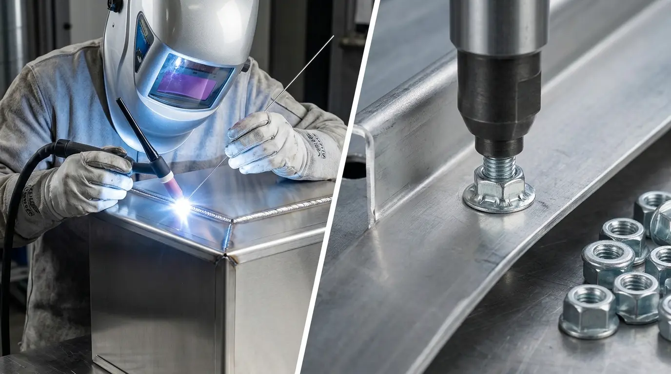
TIG Welding (GTAW): Uses a non-consumable tungsten electrode with a separately fed filler rod and inert shielding gas. TIG welding is slower than MIG but delivers superior precision, cleaner weld beads, and better aesthetic results. It is the standard for thin-gauge stainless steel and aluminum assemblies where weld appearance matters, such as architectural metalwork, medical enclosures, and consumer-facing products. Meco operates dedicated TIG welding and gas shielded welding capabilities with robotic and manual options.
Spot Welding (RSW): Joins overlapping sheets by passing high current through copper electrodes that clamp the material. The localized resistance generates enough heat to form a fused nugget between the sheets. Spot welding is extremely fast, requires no filler material, and is easily automated, making it the dominant joining method in automotive body-in-white assembly. Its main limitation is that it produces discrete point joints rather than continuous seams.
Laser Welding: Uses a focused high-energy laser beam to create deep, narrow welds with a minimal heat-affected zone (HAZ). This significantly reduces thermal distortion, which is critical for thin-gauge materials and assemblies with tight flatness requirements. Laser welding is fast, precise, and increasingly common in high-volume precision applications. Initial equipment cost is high, but throughput and quality advantages justify the investment at scale.
Resistance Welding: A broader category that includes spot welding, seam welding, and projection welding. All variants use electrical resistance to generate localized heat at the joint interface. Resistance welding excels in high-speed automated environments where repeatable, clean joints are required without filler material or shielding gas.
Mechanical Fastening
Mechanical fastening uses hardware such as screws, bolts, nuts, and threaded inserts to clamp parts together. It is the most common joining method when assemblies must be disassembled for maintenance, field repair, or component replacement.
Screws, Bolts, and Nuts: The most versatile fastening option. Self-tapping screws cut their own threads into thin sheet metal, eliminating the need for pre-tapped holes. Machine screws with nuts or threaded inserts provide stronger, more repeatable clamping force for thicker assemblies. Proper selection depends on material type, sheet thickness, required clamping load, and whether the joint must survive repeated disassembly cycles.
PEM (Self-Clinching) Fasteners: PEM nuts, studs, and standoffs are pressed into precisely punched holes. The parent sheet metal cold-flows into a knurled groove on the fastener, permanently locking it in place. This provides strong, reusable machine threads in sheets that are too thin to tap directly (typically below 2.0 mm). PEM fasteners are a cornerstone of modern electronics enclosure design, server rack assembly, and any application requiring dense hardware patterns in thin sheet metal. For detailed installation specifications and engineering data, refer to the PEM Self-Clinching Fastener Handbook (PDF) published by PennEngineering.
Threaded Inserts: Used when the base material (such as aluminum or thin-gauge steel) cannot support direct thread engagement under load. Inserts provide durable machine threads that withstand repeated fastening cycles without stripping.
Riveting
Riveting creates permanent mechanical joints by inserting a rivet through aligned holes in two or more parts and deforming one end to clamp the stack. Rivets offer excellent shear and vibration resistance and do not require heat, making them safe for assemblies with heat-sensitive components or pre-finished surfaces.
Blind (Pop) Rivets: Installed from one side of the assembly using a rivet gun, making them ideal for enclosed or limited-access geometries. The mandrel is pulled until it snaps, expanding the rivet body to form a permanent clamp.
Solid Rivets: Require access to both sides of the joint. They are stronger than blind rivets and remain standard in aerospace structural assemblies where joint integrity is paramount.
Meco's mechanical assembly services include orbital (spin) riveting, punch riveting, press riveting, and pull (blind) riveting, all integrated into dedicated assembly lines.
Clinching (Press Joining)
Clinching mechanically interlocks two or more layers of sheet metal using a punch and die, without any fasteners, heat, or consumables. The punch draws the material into the die cavity, causing it to spread laterally and form a button-shaped interlock. The result is a clean, corrosion-resistant joint produced in under one second per point.
Clinching is especially well suited for pre-painted or galvanized sheets because it does not damage surface coatings. It is widely used in HVAC ductwork, automotive subassemblies, appliance panels, and any high-volume application where speed, cleanliness, and cost efficiency are priorities. The main limitation is lower tensile strength compared to welding or riveting, which restricts clinching to light-to-moderate load applications.
Adhesive Bonding
Industrial adhesives (epoxies, acrylics, polyurethanes, and cyanoacrylates) bond sheet metal surfaces through chemical or physical interaction. Unlike mechanical fasteners or welds, adhesive bonds distribute stress uniformly across the entire bonded area rather than concentrating it at discrete points. This improves fatigue life and allows the joining of dissimilar materials such as metal to plastic, metal to composite, or different metal alloys.
Adhesive bonding also produces invisible joint lines, which makes it the preferred method when cosmetic appearance is critical. The tradeoffs are that adhesive joints require careful surface preparation (degreasing, abrasion, or chemical etching), controlled cure conditions (time, temperature, pressure), and they are not disassemblable without destroying the bond. Cure time can also slow production throughput compared to mechanical methods.
Hemming and Folding
Hemming folds the edge of one sheet over another to create a smooth, safe, reinforced edge or a mechanical joint between two panels. Open hems fold the edge partially; closed hems fold it flat against itself for maximum rigidity. Hemming is standard in automotive door panels, appliance housings, and any assembly where exposed sharp edges are unacceptable. It reduces part count by eliminating the need for separate edge trim and improves stiffness without adding weight.
Tab and Slot Assembly
Tab and slot is a self-locating design feature where tabs laser-cut into one part are inserted into corresponding slots on the mating part. The interlocking geometry holds components in alignment before permanent joining (typically welding or fastening). This self-fixturing approach reduces or eliminates the need for external clamps and jigs, which speeds assembly, improves repeatability, and lowers fixture tooling costs. Tab and slot design is especially effective in laser-cut assemblies produced by custom laser cutting services because the tab geometry can be integrated directly into the cutting program at zero additional cost.
Snap-Fit Joints
Snap-fit joints use the elastic deflection of a cantilevered feature on one part to engage a mating feature on another. The tab flexes during insertion and snaps into a locked position. This is the fastest assembly method because it requires no hardware, tools, or consumables. Snap-fit joints are common in battery covers, access panels, lightweight enclosures, and consumer products where fast tool-free assembly or disassembly is required. They are limited to light-to-moderate loads and require careful material selection to avoid fatigue cracking from repeated engagement cycles.
Sheet Metal Assembly Technique Comparison
Selecting the right joining method requires balancing strength, cost, speed, serviceability, and material compatibility. The following table provides a direct comparison across every major technique to support faster sourcing and design decisions.
| Technique | Joint Type | Strength | Speed | Disassembly | Best For | Limitations |
|---|---|---|---|---|---|---|
| MIG Welding | Permanent | Excellent | Fast | No | Structural frames, brackets, medium-to-thick gauge | Heat distortion, post-weld grinding may be needed |
| TIG Welding | Permanent | Excellent | Slow | No | Thin-gauge stainless steel and aluminum, cosmetic welds | Slower, higher operator skill required |
| Spot Welding | Permanent | Good | Very Fast | No | Automotive panels, overlapping sheets, high-volume | Point joints only, not suitable for sealed seams |
| Laser Welding | Permanent | Excellent | Very Fast | No | Precision assemblies, thin materials, low distortion | High equipment cost |
| Screws / Bolts | Removable | Good to Excellent | Medium | Yes | Serviceable enclosures, multi-material assemblies | Hardware cost, visible fastener heads |
| PEM Fasteners | Permanent insert, removable joint | Good | Fast | Yes | Thin sheet electronics enclosures, server racks | Requires precise hole sizing |
| Blind Rivets | Permanent | Good | Fast | No | Limited-access joints, sheet metal to sheet metal | Protruding rivet tail on back side |
| Clinching | Permanent | Moderate | Very Fast | No | HVAC, pre-coated sheets, high-volume light-duty | Lower tensile strength than welding or riveting |
| Adhesive Bonding | Permanent | Good (shear) | Slow (cure time) | No | Cosmetic assemblies, dissimilar materials, vibration damping | Surface prep sensitive, cure time slows throughput |
| Tab and Slot | Self-locating (paired with welding/fastening) | Moderate alone | Very Fast | No | Laser-cut assemblies, high-repeatability fixturing | Requires permanent joining method for final strength |
| Hemming | Permanent | Moderate | Fast | No | Edge finishing, automotive panels, appliance housings | Limited to edge-joining geometry |
| Snap-Fit | Removable | Low to Moderate | Very Fast | Yes | Access panels, battery covers, light enclosures | Fatigue risk with repeated use, light loads only |
Sheet Metal Assembly Tolerances: Standards, Ranges, and Stack-Up
Tolerances define the acceptable dimensional deviation between a designed dimension and the actual manufactured result. In sheet metal assembly, tolerances matter more than in single-part fabrication because individual part deviations accumulate when multiple components are joined together. Understanding tolerance standards, achievable ranges by process, and stack-up analysis principles is essential for any engineer or sourcing manager specifying sheet metal assemblies.
Governing Standards
The most widely referenced tolerance standard for sheet metal fabrication is ISO 2768, which defines general tolerances for linear dimensions, angular dimensions, and geometrical characteristics (flatness, straightness, perpendicularity, symmetry, and circular runout). ISO 2768 has two parts: Part 1 covers linear and angular tolerances across four classes (f = fine, m = medium, c = coarse, v = very coarse), and Part 2 covers geometrical tolerances across three classes (H, K, L). The most commonly specified combination for sheet metal work is ISO 2768-mK, meaning medium-class linear tolerances and K-class geometrical tolerances.
Other applicable standards include ASME Y14.5 (GD&T for North American engineering drawings), DIN 6930-2 (tolerances for stamped and blanked parts), GB/T 13914 (Chinese national standard for stamping tolerances used in Asian manufacturing), and ASTM B633, ASTM A123, and MIL-A-8625 for surface finish specifications that affect final assembly dimensions.
Typical Tolerance Ranges by Process
| Process | Dimensional Tolerance | Angular Tolerance | Notes |
|---|---|---|---|
| Laser Cutting | +/-0.05 to +/-0.1 mm | N/A | Tighter on thin gauge; edge quality depends on material and gas assist |
| CNC Punching | +/-0.1 to +/-0.25 mm | N/A | Hole-to-hole accuracy depends on turret indexing |
| CNC Press Brake Bending | +/-0.1 to +/-0.2 mm (linear) | +/-0.5 degrees | Tighter tolerances require back-gauge compensation and in-process measurement |
| Stamping / Progressive Die | +/-0.05 to +/-0.15 mm | +/-0.5 degrees | Best accuracy at high volume with hardened tooling per DIN 6930 |
| Hardware Insertion (PEM) | +/-0.05 mm (hole center) | N/A | Hole diameter must follow manufacturer's specification exactly |
| Welded Assembly | +/-0.25 to +/-0.5 mm | +/-1.0 degree | Distortion depends on weld method, heat input, and fixturing quality |
| Overall Assembly (multi-part) | +/-0.5 to +/-1.0 mm typical | +/-1.0 degree typical | Driven by tolerance stack-up across all contributing parts and joints |

Tolerance Stack-Up in Sheet Metal Assemblies
Tolerance stack-up is the cumulative effect of individual part tolerances on the final assembly dimension. It is the single most common source of fit problems in multi-part sheet metal assemblies and the reason why parts that individually pass inspection can still fail to assemble correctly.
There are two primary methods for calculating stack-up. Worst-case (arithmetic) analysis adds all individual tolerances together to find the maximum possible deviation. This approach is conservative and guarantees 100% assembly success, but it can make designs unnecessarily expensive because it assumes every part is simultaneously at its extreme limit. Root Sum Square (RSS) statistical analysis calculates the square root of the sum of squared individual tolerances. RSS reflects the statistical reality that not all parts will be at their extreme limits simultaneously, and it predicts the deviation that roughly 99.73% of assemblies (3-sigma) will fall within. Most production sheet metal programs use RSS because it balances cost and quality risk effectively.
For example, an assembly with five individual features each toleranced at +/-0.1 mm has a worst-case stack-up of +/-0.5 mm but an RSS stack-up of only +/-0.22 mm. Understanding this difference allows engineers to specify tighter overall assembly tolerances without requiring unnecessarily tight (and expensive) individual part tolerances.
Strategies for Managing Tolerance Stack-Up
Use self-locating features (tab and slot, dowel pins) to eliminate positional variation between parts. Design datum schemes that minimize the number of tolerance contributors in critical dimensions. Specify GD&T per ASME Y14.5 rather than bilateral linear tolerances for features that control assembly fit. Use slotted holes rather than round holes for one of the two mating features at bolted joints to absorb positional variation.
Materials for Sheet Metal Assembly
Material selection for sheet metal assemblies depends on the balance of strength, weight, corrosion resistance, formability, weldability, and cost that each application demands. The following table summarizes the most commonly used sheet metal materials, their key properties, and the joining methods they are compatible with.
| Material | Key Properties | Common Gauges | Compatible Joining Methods | Typical Applications |
|---|---|---|---|---|
| Mild / Carbon Steel | High strength, low cost, excellent weldability | 16 ga to 10 ga (1.5 to 3.4 mm) | All welding types, riveting, fasteners, clinching, adhesive | Chassis, brackets, frames, structural enclosures |
| Stainless Steel (304, 316) | Corrosion resistant, hygienic, durable | 18 ga to 12 ga (1.2 to 2.7 mm) | TIG welding preferred; spot welding, fasteners, PEM hardware | Food equipment, medical enclosures, architectural panels |
| Aluminum (5052, 6061) | Lightweight, corrosion resistant, thermally conductive | 18 ga to 10 ga (1.0 to 2.6 mm) | TIG/MIG welding (specialized), riveting, PEM fasteners, adhesive | Electronics enclosures, aerospace panels, heat sinks |
| Galvanized Steel | Pre-coated corrosion protection, weldable with precautions | 20 ga to 12 ga (0.9 to 2.7 mm) | Spot welding, riveting, clinching, fasteners | HVAC ductwork, outdoor enclosures, agricultural equipment |
| Copper | High electrical/thermal conductivity | 20 ga to 14 ga (0.8 to 1.6 mm) | TIG welding, soldering, riveting, fasteners | Bus bars, heat exchangers, electrical enclosures |
| Brass | Excellent machinability, decorative finish, conductive | 20 ga to 14 ga (0.8 to 1.6 mm) | TIG welding, riveting, fasteners, adhesive | Electrical connectors, decorative panels, fittings |
Material choice also directly affects surface finishing options. Aluminum supports anodizing (Type II and Type III per MIL-A-8625). Steel supports zinc plating (per ASTM B633), galvanizing, powder coating, e-coating, and painting. Stainless steel is often used unfinished or with electropolishing for hygienic applications. For a full material-to-finish compatibility matrix, refer to Meco's surface finishing services page.
Design for Sheet Metal Assembly: 10 DFM Rules That Reduce Cost and Improve Quality
Design for Manufacturability and Assembly (DFMA) is not a theoretical exercise. In sheet metal fabrication, applying the right design rules at the drawing stage directly reduces tooling cost, assembly labor, scrap rate, and time to market. The following ten rules are drawn from real production experience and should be applied to every new sheet metal assembly program.
1. Minimize part count. Every additional part adds a cutting operation, a forming operation, a handling step, and an assembly operation. Consolidate two brackets into one formed part wherever geometry allows. Reducing a 12-part assembly to 8 parts can cut assembly labor by 30% or more.
2. Use self-locating features. Design tab-and-slot, tongue-and-groove, or embossed locating features into the sheet metal parts themselves. Self-locating geometry reduces fixture cost, eliminates manual alignment, and improves repeatability.
3. Standardize fastener types and sizes. Every unique screw size or fastener type adds a bin to the assembly station, a tool change, and a potential for operator error. Standardize on the fewest possible fastener variants.
4. Maintain minimum bend radius. The minimum inside bend radius for sheet metal is generally equal to the material thickness (1T) for mild steel and 1.5T to 2T for aluminum and stainless steel. Specifying a radius below minimum risks cracking on the outside of the bend.
5. Keep holes away from bends. Holes located too close to a bend line will distort during forming. The general rule is to maintain a minimum distance of 2.5 times the material thickness plus the bend radius from the edge of any hole to the nearest bend line.
6. Design for unidirectional assembly. Arrange all components so they can be inserted from a single direction (typically top-down). This simplifies both manual and robotic assembly, eliminates the need to flip or rotate the workpiece, and reduces cycle time.
7. Ensure tool access. Verify that every fastener, rivet, and weld joint is accessible to the required tool (screwdriver, rivet gun, weld torch, or robot end effector). Inaccessible joints are the most common cause of assembly-line stoppages and design revisions after tooling is built.
8. Specify tolerances based on function, not habit. Over-tolerancing individual parts drives up fabrication cost. Use tolerance stack-up analysis to determine the actual tolerance each feature needs to contribute to the overall assembly requirement, and specify only that.
9. Plan finishing before assembly. Decide which parts receive surface treatment before joining and which are finished after. Coating thickness affects hole diameters, thread engagement, and mating surface fit. Masking requirements must be defined on the drawing.
10. Request DFM feedback from your manufacturer before releasing drawings. A 15-minute DFM review can prevent weeks of rework. Experienced fabricators spot problems such as undercut bend sequences, incompatible material-to-process combinations, and unnecessary tight tolerances that inflate cost without adding functional value. Meco provides DFM analysis as part of its standard R&D engineering and quoting workflow, with feedback delivered alongside every quote.
Which Industries Use Sheet Metal Assemblies?
Sheet metal assemblies serve virtually every manufacturing sector. The specific requirements vary by industry, but the underlying need is the same: reliable, repeatable, dimensionally accurate assemblies delivered on time and at competitive cost.
Automotive: Body panels, structural brackets, battery enclosures for EVs, exhaust heat shields, interior trim supports, and HVAC housings. Automotive sheet metal assembly demands high-volume repeatability, tight tolerances (often +/-0.1 mm on critical features), PPAP documentation, and IATF 16949:2016 certified quality systems. Meco serves the automotive industry with IATF 16949:2016 certified processes and tolerances to +/-0.01 mm on machined features.
Aerospace: Aircraft fuselage panels, avionics enclosures, structural ribs, bracket assemblies, and satellite housings. Aerospace requires full material traceability, NDT (ultrasonic, dye penetrant, X-ray), FAIR/PPAP documentation, and tight dimensional control. Riveting is the dominant joining method for airframe structures due to its fatigue performance and inspectability. Meco supports aerospace manufacturing with CMM inspection, SPC, full lot/serial traceability, and calibrated NDT processes.
Electronics and Telecommunications: Server racks, control panels, EMI/RFI shielding enclosures, 19-inch rack-mount chassis, and cable management housings. Electronics sheet metal assemblies rely heavily on PEM hardware, powder-coated or anodized finishes, and tight dimensional control for PCB mounting. Meco provides custom electronics manufacturing and PCB design and assembly integrated with sheet metal fabrication.
Industrial and Heavy Equipment: Machine guards, operator cabins, control enclosures, conveyor housings, and structural weldments for construction, mining, and agricultural machinery. Industrial sheet metal assemblies often combine thick-gauge steel fabrication with welding, powder coating, and hardware insertion. Tolerances are typically more forgiving than in electronics or aerospace, but durability and corrosion resistance requirements are higher. Meco serves heavy equipment and industrial manufacturing with 40+ processes under one roof.
Medical Equipment: Diagnostic device housings, surgical equipment enclosures, patient bed frames, and sterilization-compatible cabinets. Medical assemblies require clean cosmetic finishes (typically powder coat or paint), full documentation and traceability, and materials that withstand repeated cleaning or sterilization.
Home Appliances and HVAC: Oven liners, refrigerator panels, washer drums, HVAC duct assemblies, and fan housings. High-volume appliance assembly often uses spot welding, clinching, and progressive stamping for cost efficiency, with powder coating or e-coating for corrosion protection. Meco provides home appliance manufacturing capabilities spanning stamping, molding, assembly, and finishing.
When to Outsource Sheet Metal Assembly
Not every organization should build sheet metal assemblies in-house. The capital cost of laser cutters, press brakes, welding cells, finishing lines, and assembly stations is substantial. Beyond equipment, maintaining a skilled workforce, quality system, and supply chain for raw materials and fasteners adds further overhead. Outsourcing sheet metal assembly to a contract manufacturing partner makes sense in several scenarios.
The first is when production volumes fluctuate. Maintaining an in-house line that runs at 30% utilization six months of the year is far more expensive per unit than paying a contract manufacturer to absorb demand peaks and valleys. The second is when multiple fabrication processes are involved. If your assembly requires laser cutting, bending, welding, hardware insertion, powder coating, and final assembly, coordinating five separate vendors creates lead time risk, quality gaps at handoff points, and logistical complexity. A single turnkey manufacturing partner eliminates that fragmentation.
The third scenario is when speed matters. A contract manufacturer with existing tooling, trained operators, and raw material inventory can ramp production faster than an internal team starting from a bare floor. Meco delivers quotes in under 24 hours, prototypes in 1 to 2 weeks, and tooling in 3 to 6 weeks, with production facilities totaling 36,000 m² across Thailand and China.
The fourth is when quality system requirements exceed internal capability. OEM customers in automotive, aerospace, and medical often require PPAP documentation, CMM inspection reports, full lot traceability, SPC data, and certified quality management systems. Building those systems internally can take years. Meco's IATF 16949:2016 certification covers the full manufacturing workflow from incoming inspection through final delivery.
How to Choose a Sheet Metal Assembly Partner
The right manufacturing partner for sheet metal assemblies is not just a fabrication shop that can cut and bend. They must connect upstream processes (cutting, forming, machining, finishing) with downstream assembly, inspection, packaging, and logistics into a single accountable workflow. Evaluating a potential partner should focus on these criteria.
Process breadth: Can the supplier handle every fabrication step in-house, or will they subcontract cutting to one vendor, finishing to another, and assembly to a third? Subcontracting creates quality handoff gaps and extends lead times. Look for a manufacturer with laser cutting, CNC bending, stamping, welding, surface finishing, and assembly under one roof.
Quality certification: IATF 16949:2016 is the most rigorous quality management standard in manufacturing, built upon all ISO 9001:2015 requirements and adding automotive-specific controls for APQP, PPAP, SPC, PFMEA, and continuous improvement. A manufacturer certified to IATF 16949:2016 applies that discipline across every industry they serve, not just automotive.
Engineering support: DFM review, tolerance analysis, fixture design, and process optimization should happen before production starts, not after the first batch fails inspection. The best partners include engineering as a standard part of the quoting process.
Scalability: Your partner should handle 10-piece prototypes and 10-million-piece production runs with equal reliability. No minimum order quantities, clear prototype-to-production transition plans, and flexible scheduling for demand variation are essential.
Logistics integration: Can the partner warehouse finished goods, manage JIT delivery schedules, and ship to multiple destinations? If your assemblies ship to North America, Asia, and Europe, you need a partner with warehousing in the right regions.
Meco checks every one of these boxes. With 30+ years of turnkey manufacturing experience, IATF 16949:2016 certified facilities in Thailand (20,000 m²) and China (16,000 m²), U.S. engineering support, 40+ manufacturing processes, and warehousing in the U.S. (Ohio and Florida), Canada, Japan (Tokyo and Osaka), and Thailand, Meco provides a single point of accountability from concept through global delivery. To learn more about Meco's integrated capabilities, visit About Us or read about what mechanical assembly involves in Meco's detailed engineering guide.
Frequently Asked Questions About Sheet Metal Assembly
What is the difference between sheet metal fabrication and sheet metal assembly?
Sheet metal fabrication refers to the processes that shape individual parts from flat sheet stock, including cutting, bending, punching, stamping, and forming. Sheet metal assembly is the subsequent stage where those individually fabricated parts are joined together into a finished product or subassembly using techniques such as welding, riveting, fastening, clinching, or adhesive bonding. In practice, most manufacturing programs require both fabrication and assembly, which is why turnkey partners that handle the full workflow from flat sheet to finished product reduce lead times and quality risk compared to using separate vendors for each stage.
What tolerances can be held in sheet metal assembly?
Typical overall sheet metal assembly tolerances range from +/-0.5 mm to +/-1.0 mm, depending on the number of parts, the joining method, and the quality of fixturing. Individual process tolerances are tighter: laser cutting holds +/-0.05 to 0.1 mm, CNC press brake bending holds +/-0.1 to 0.2 mm linear and +/-0.5 degrees angular, and stamping holds +/-0.05 to 0.15 mm. The general tolerance standard ISO 2768-mK is widely referenced for sheet metal work. Assembly tolerances are ultimately governed by tolerance stack-up across all contributing parts, which is why DFM review and stack-up analysis before production are critical for assemblies with tight fit requirements.
What are the most common sheet metal assembly methods?
The most common methods are welding (MIG, TIG, spot, laser, and resistance), mechanical fastening (screws, bolts, PEM self-clinching hardware, and threaded inserts), riveting (blind and solid), clinching (press joining without hardware), adhesive bonding, hemming and folding, tab-and-slot self-fixturing, and snap-fit joints. The optimal method depends on joint strength requirements, whether the assembly needs to be disassembled for service, production volume, material type, and cosmetic requirements. Many assemblies use a combination of methods, such as tab-and-slot alignment followed by spot welding for permanent joining.
What is tolerance stack-up in sheet metal assembly?
Tolerance stack-up is the cumulative effect of individual part tolerances on a final assembly dimension. When multiple parts are joined, their individual dimensional deviations add together along the measurement chain. Worst-case analysis adds all tolerances arithmetically, which is conservative but can lead to over-engineering. RSS (Root Sum Square) analysis calculates the statistical combination and provides a more realistic prediction of assembly variation. For example, five parts each at +/-0.1 mm produce a worst-case stack of +/-0.5 mm but an RSS stack of only +/-0.22 mm. Managing tolerance stack-up through self-locating features, datum planning, and GD&T is the key to producing sheet metal assemblies that fit correctly at production volumes.
What materials are used in sheet metal assemblies?
The most common materials are mild steel (strong, low cost, weldable), stainless steel (corrosion resistant, hygienic), aluminum (lightweight, thermally conductive), galvanized steel (pre-coated corrosion resistance), copper (electrically conductive), and brass (machinable, decorative). Material selection determines which cutting, forming, joining, and finishing processes are compatible. For instance, aluminum requires specialized TIG or MIG welding techniques due to its high thermal conductivity, and thin aluminum sheets benefit from PEM self-clinching fasteners rather than tapped holes because the threads are more likely to strip under load.
When should I outsource sheet metal assembly instead of building in-house?
Outsourcing makes sense when production volumes fluctuate (avoiding underutilized capital equipment), when your assembly requires multiple processes from different specialties (cutting, bending, welding, finishing, and hardware insertion), when speed to market is critical and a contract manufacturer has existing capacity, or when quality documentation requirements such as PPAP, FAI, CMM reports, and IATF 16949:2016 certification exceed internal capability. A turnkey partner that handles every step from raw sheet to delivered assembly eliminates vendor coordination overhead and reduces the quality risk at handoff points between separate suppliers.
What is the standard process flow for sheet metal manufacturing and assembly?
The standard process flow is: (1) material selection and preparation, (2) cutting (laser, punch, shear, or plasma), (3) forming and bending (CNC press brake or stamping), (4) secondary machining if required (drilling, tapping, milling), (5) surface finishing (powder coating, plating, anodizing, painting), (6) assembly (welding, fastening, riveting, or clinching), (7) quality inspection and documentation (CMM, FAI, PPAP), and (8) packaging and delivery. Each upstream step affects assembly quality, which is why integrated manufacturers who control the full flow deliver better results than fragmented supply chains where different vendors handle each stage independently.
What is sheet metal bending and what tolerances can bending services achieve?
Sheet metal bending is the process of forming a flat blank into a three-dimensional shape by applying force along a linear axis using a CNC press brake or similar forming equipment. Standard CNC press brake bending tolerances are +/-0.5 degrees on bend angle and +/-0.1 to 0.2 mm on linear bend dimensions for most common materials and gauges. Tighter tolerances are achievable with high-precision tooling, in-process angle measurement, and back-gauge compensation, but they increase per-part cost. Factors that affect bending accuracy include material type, thickness, grain direction, tooling condition, and whether the bend sequence allows the part to be fully supported at each stage.
Get Your Sheet Metal Assemblies Built Right the First Time
Coordinating separate vendors for cutting, bending, welding, finishing, and assembly creates lead time risk, quality gaps, and unnecessary cost. Meco eliminates that complexity by managing the entire sheet metal assembly workflow under one roof, from raw material to globally delivered finished product.
With 30+ years of turnkey manufacturing experience and IATF 16949:2016 certified quality, Meco is built for OEM programs where precision, traceability, and on-time delivery are non-negotiable.
- 40+ In-House Processes: Laser cutting, CNC bending, stamping, welding (TIG, MIG, spot, laser, resistance), surface finishing, mechanical assembly, and electromechanical integration.
- IATF 16949:2016 Certified: Automotive-grade quality applied across every industry. 99.99% quality rate. 99.8% on-time delivery.
- DFM Feedback with Every Quote: Engineering review included as standard, with quotes returned in under 24 hours.
- Prototype to Mass Production: From 10 pieces to 10 million+. No minimum order quantities.
- Global Logistics: Warehousing in the U.S. (Ohio & Florida), Canada, Japan (Tokyo & Osaka), and Thailand. JIT and VMI delivery programs available.
Submit your drawings and let Meco's engineering team show you how to reduce cost, shorten lead times, and consolidate your sheet metal supply chain into one accountable partner.
Request a Quote Today