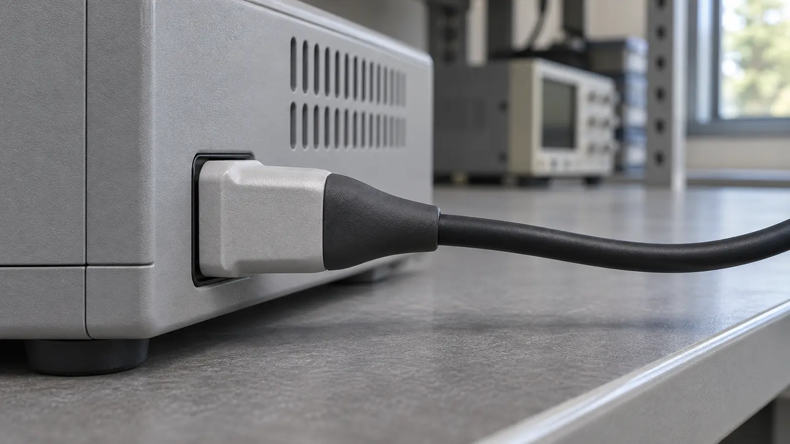
Overmolding is a way to mold one material directly onto a part that already has its shape. This lets each material do a different job. The base can give the part its strength, and the added layer can improve grip or help form a seal.
Molding the layer in place can save the step of attaching a separate piece. Before making the mold, plan how to test that the two materials stay together during use.
Think of a handheld controller used in a workshop. Its shell has to keep the buttons in place, while the sides need enough grip to hold it with a wet glove.
You could fit a sleeve over the shell or add a molded grip just where the fingers rest. A sleeve can be replaced if it wears, while a molded grip stays with the shell and can follow its shape.
That choice affects what you pay for the mold, what you assemble later, and what you have to check on the first parts.
Meco's plastic injection molding guide explains how a mold shapes a single plastic part. The controller example shows what changes when the mold also has to work around a part that already has a shape.
Key takeaways
- Start with the job. Name what the added material must do, such as add grip, take up a small gap, or help a cable bend near a plug.
- Plan the molding route. The base can come from a separate run or move straight to a second injection stage on the same machine.
- Check both material grades. The exact grades, how they are molded, and how the part will be used all affect the joint.
- Draw the boundary. Show where the added layer ends, where the mold can hold the base, and which surfaces need to stay clear.
- Test the job the part does. Check the joint, fit, and function on molded samples under conditions that reflect real use.
What is overmolding?
In overmolding, a mold holds a shaped part, called the substrate, while a second material takes shape against it. The added layer is the overmold, and the interface is the area where it touches the substrate, including the grip edge.
The mold leaves room for the new material only where the design calls for it. As that space fills, the new layer takes the shape of both the tool and the shell beneath it. It can cover a small patch, wrap around an edge, or surround much of the base.
The added layer can be soft, as on a grip, or rigid, as on a colored detail molded into a hard panel. What matters is how the two materials share the work. On the controller, the soft strip can flex while the screw seats and button openings remain in the rigid shell.
The shell has to be in the right place before the strip can form. The two common molding routes differ in how they bring the shell into position.
How does the overmolding process work?
The mold locates the base part, the second material fills the space around it, and the finished part comes out once it can hold its shape.
- Form the base. Mold the rigid shell so it has the features needed to sit in the next cavity. A cavity is the open space inside a mold that gives the part its shape.
- Position the base. The tool holds the shell in a set position. It must stay there when the pressure of the next shot pushes on it. A shot is one injection of material.
- Inject the outer layer. The material enters through a small opening called a gate. It flows over the planned area while small vents let displaced air out.
- Cool and remove the part. In a typical thermoplastic process, both materials are ready to come out once they are firm enough to keep their shape. A thermoplastic softens when heated and firms up again as it cools.
Pick-and-place and two-shot molding
In pick-and-place overmolding, the base is made ahead of time. A person or a robot places it in the tool for the next shot. The shop can use this setup to mold shells in one run and add the grip in a separate run.
In two-shot molding, also called 2K molding, the second shot follows the first within one machine cycle. In one common setup, part of the tool rotates to carry the base into position. Meco's two-shot molding guide shows how those tools move the first part between shots.
| Route | Where the base comes from | What to check |
|---|---|---|
| Pick-and-place | A base part made before the second molding step | Loading time, how the base sits in the tool, and its surface condition at loading |
| Two-shot (2K) | The first shot in the same machine cycle | Tool and machine needs, how the part transfers, and the time between shots |
Between runs, a preformed shell may cool and change size slightly, which can affect how it seats in the second tool. A two-shot setup usually gives the shell less time to cool before the next shot. The shop needs to check fit and bonding under the conditions of the chosen route.
Where insert molding fits
A threaded brass piece can be placed in a mold before plastic flows around it. This is commonly called insert molding.
The metal gives a screw a place to fasten, and its shape helps hold it in the plastic. For threaded parts, see our guide to designing parts with metal inserts.
Shops may use the words insert molding and overmolding for overlapping processes. On a drawing or quote request, say what goes into the tool, what flows around it, and what each part does. That tells the shop what kind of joint the part needs. Our overmolding vs. insert molding guide compares when to use each approach.
Which materials can work together?
Choose a base that holds the part's shape and an outer material that does the job at the surface. Then check how the exact pair will stay joined.
Choose each material by its job
A rigid shell might start with ABS, a plastic often used for housings, or polycarbonate (PC), a plastic often chosen for impact resistance. The right grade depends on the load the shell carries and the temperatures, chemicals, and impacts it may face.
Many grips use a thermoplastic elastomer (TPE), a material that feels rubbery and can be shaped with heat in a molding machine. Thermoplastic polyurethane (TPU) is a type of TPE. Some TPU grades suit parts that rub against other surfaces, so wear can help guide the choice.
Hardness tells you how much a material resists a dent when pressed. A lower hardness often feels softer when you press on the grip. For a grip, you still need to check how well it holds in the conditions you expect, such as when it is wet or used with gloves.
Our TPE overmolding guide explains how to choose a grade for grip, sealing, or other uses.
Meco's injection molding materials guide gives an overview of resin families. Use the family name to narrow the options, then ask the resin supplier for data on the exact base and outer grades.
Decide how the layer will stay on
- Adhesion. Some grades form a bond at the surface during molding. The exact pair, how warm the base is, and whether oil or mold release is present can all affect the bond. Mold release is a substance used to help a part come out of a tool.
- Mechanical retention. The outer layer can flow through a hole or around a lip in the base. Once it firms up, the shape helps lock it in place. The hole or lip needs enough room to fill, and the base still needs enough strength for its job.
A grip can use both methods, with adhesion across the surface and a small mechanical lock near an edge that sees extra force. Resin supplier data helps screen the grades, while a test on the actual geometry checks how the joint holds where a hand pulls or rubs.
Our guide to material compatibility and bonding explains how to check a specific pair. The drawing needs to show where the edge will be.
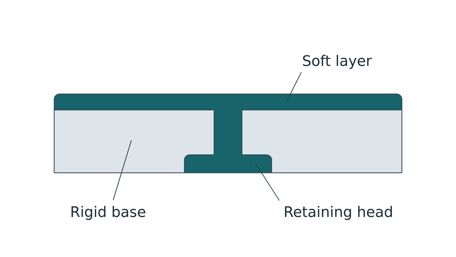
What should you check before tooling?
Show where the outer layer starts and stops, how the mold will hold the base, and where the finished part must still fit.
- Mark the shut-off. This is the spot where the mold presses against the base to stop the new material. A gap there can leave flash, a thin fringe of excess plastic. Keep the boundary clear of screw seats and other areas that must stay bare.
- Protect the edge. An exposed corner can catch on a glove or on the edge of a case. A small ledge in the hard shell can shelter the end of the grip. Check that the ledge still leaves space for the soft layer to fill.
- Keep thickness changes gradual. Thin areas may be hard to fill, and thick areas may take longer to cool. If the layers shrink by different amounts, the cover can warp as it cools and leave a gap at the joint.
- Give the base support. Give the mold a firm place to hold the base because a thin wall can bend or shift under the force of the next shot. A slight slope on a wall, called draft, can also help the finished part slide out of the tool.
Drawing check
For the controller, show the grip edge, button openings, screw seats, and the flat face that meets the other shell. Mark which dimensions apply after both materials have been molded. Our overmolding design guidelines cover wall thickness, shut-offs, and how to support the base in the tool.
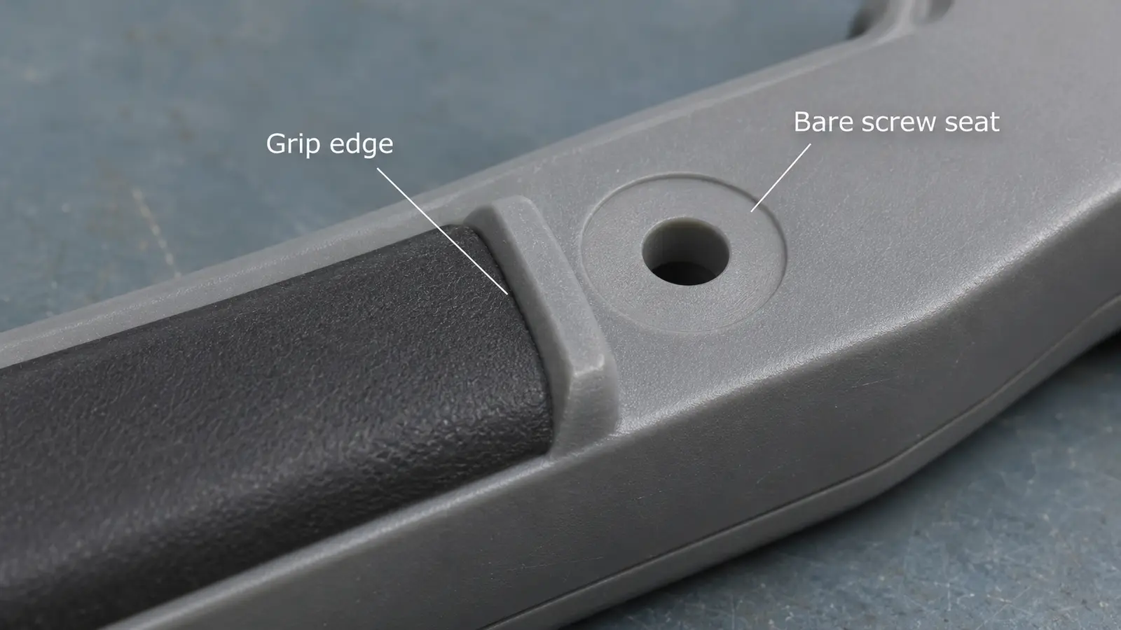
These are the kinds of details a design for manufacturing (DFM) review checks before the tool is made. Meco's R&D engineering service covers design and sample planning. The mold review can also show how much extra work the second layer adds.
Planning a two-material part? Share the base and overmold drawing and what the surface must do. Meco can review how the part would be molded and which details to check before tooling.
Talk to an EngineerWhen does the added layer pay off?
It earns its place when it gives the product a clear benefit or removes a fitting step that would otherwise add time or parts.
- Grip. A molded strip can follow the curve of a handle and stay in the area your fingers use. Check it with the gloves, moisture, or cleaning products it will see.
- Sealing. A soft rim can form part of a lid seal. The mating part still has to squeeze the rim enough when closed, so test the assembled lid for leaks under the planned conditions.
- Cable support. A molded boot can spread the bend where a cable leaves a connector. Check how the boot grips the cable jacket and how the cable holds up after repeated bends.
For a grip that must be easy to replace, a separate sleeve can be a better fit. A texture molded into a single hard plastic may also give enough grip for a dry indoor part. Meco's mechanical assembly guide explains joining methods to consider when a second piece stays separate.
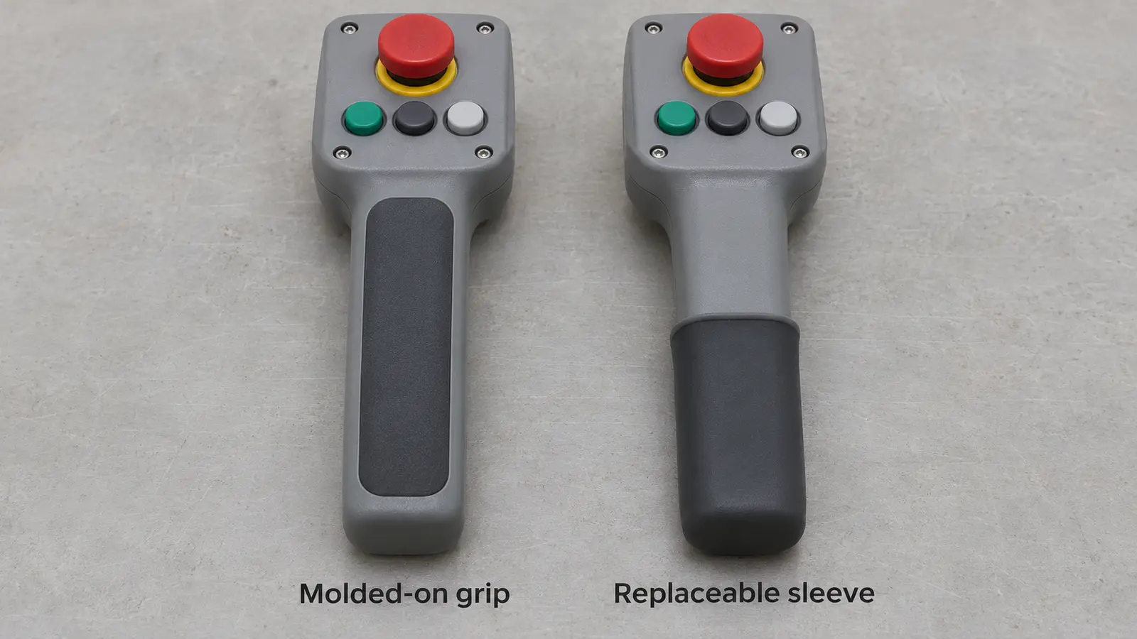
When comparing quotes, ask for the mold cost and part price as separate lines. Include any time spent loading the base, fitting a separate piece, or checking the finished part. A combined design can save a fitting step during production, but a change to the grip may also require a tool change.
Compare the full cost over the quantity you expect to sell. On a short run, an off-the-shelf sleeve may cost less overall because it avoids a dedicated tool for the grip. First samples can show whether the added layer delivers the benefit that justified the investment.
What do first molded samples tell you?
A trial part shows whether the layer fills, stays attached, and still lets the product work as drawn.
- Look along the boundary. Check for a bare patch where the layer did not fill, a thin fringe of flash, or a grip that sits off to one side. Mark where the sign appears and whether it repeats on more than one part.
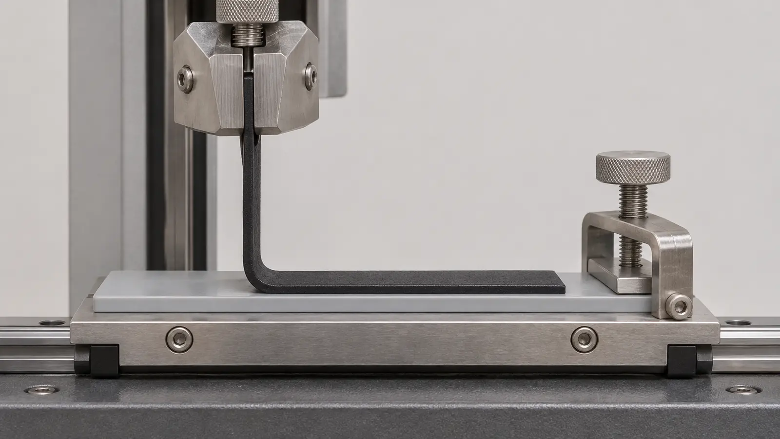
- Check the joint. Agree on how to load the joint and what counts as a pass. A peel test measures the force needed to lift a flexible edge under set conditions. Repeating it after exposure to a cleaner or to heat can show how the bond changes during use.
- Check the finished fit and function. Fit both halves of the controller together and check that the buttons move freely. For a seal or cable boot, use a leak or bend test that matches the job the part will do.
Flash at the grip edge could come from a shell that shifted or from a gap where the tool closes against it. Meco's injection molding defects guide explains how common molding defects form.
Photos and notes from the trial help the shop check how the base was seated before changing a setting. Record the material grades and sample batch as well, so the next trial can be compared with the first.
Use our guide to troubleshooting overmolding defects to narrow down problems at the joint, such as peeling or an incomplete fill.
What should you send a manufacturer?
Send the part geometry and the conditions it must work in so the shop can review the molding route and plan the first checks.
- Part files. A 3D model or a drawing showing the base, the added layer, and the areas that must stay bare.
- Materials. Exact grades if chosen, or the stiffness, feel, and exposure the part has to handle.
- Critical features. Fit dimensions, areas that must look clean, and the edges that must resist lifting.
- Use and test plan. How the part will be held, cleaned, bent, or sealed, and the checks you want on samples.
- Quantities. First batch size and expected annual orders. These help the shop compare manual loading with a more automated route.
Meco's custom injection molding services cover overmolding, insert molding, and two-shot molding. Meco provides DFM feedback with each quote. For a controller shell, ask the team to review where the grip ends and how the tool can support the shell during the second shot. A marked-up drawing helps make those points clear before anyone sets the tool layout.
Review Your Overmolded Part
Share a drawing, the intended use, and the checks that matter to your part. Meco can review molding options and discuss what to verify on the first samples.
- Design review. DFM feedback with each quote
- Sample records. First article inspection reports available
- Design protection. Nondisclosure agreement available before file sharing
References and sources
- Avient. Overmolding: Part Design. Guidance on part thickness, shut-offs, and mechanical retention.
- Avient. Overmolding: Processing. Guidance on adhesion, base temperature, and surface preparation.
