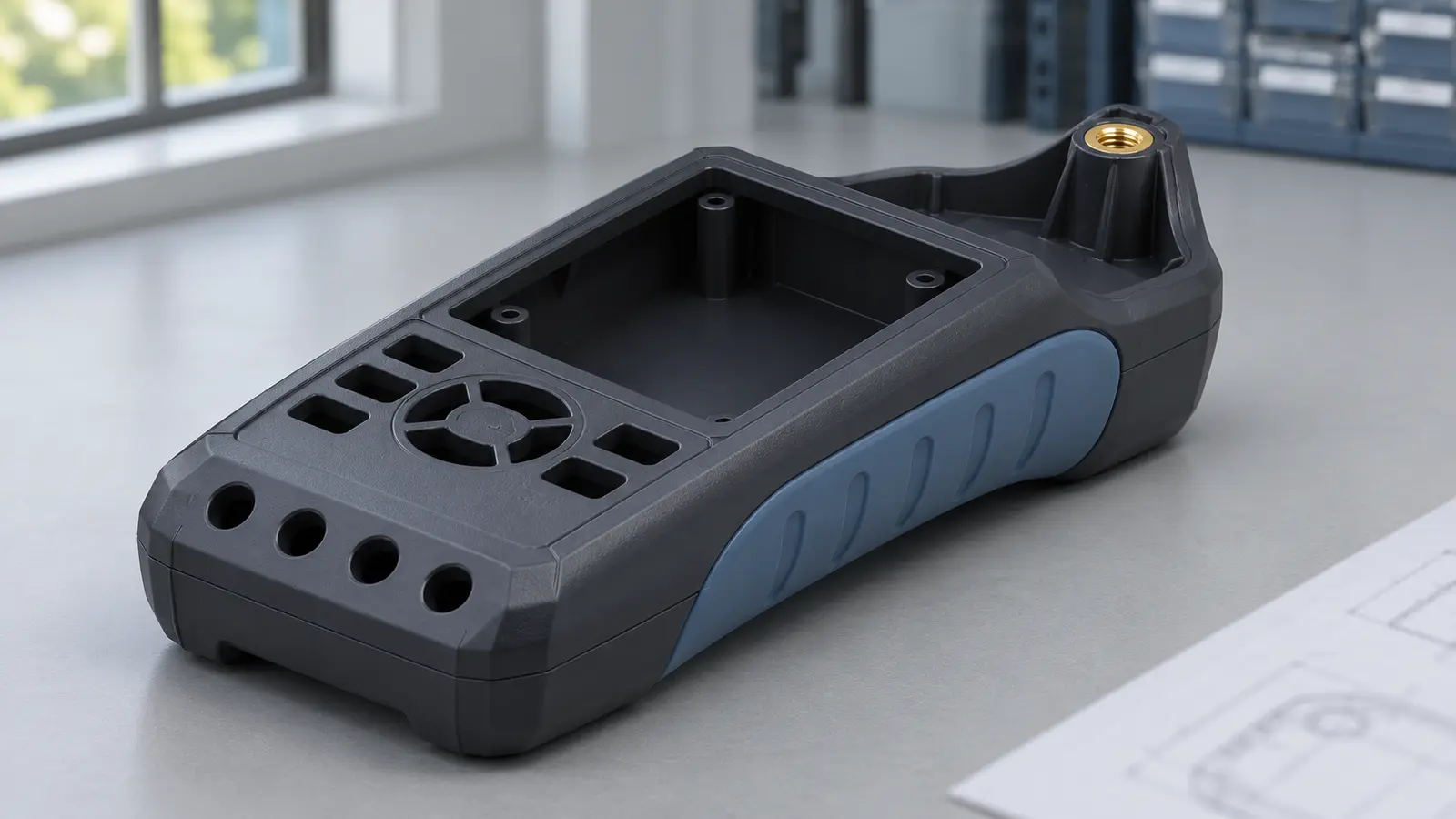
For overmolding vs insert molding, start with the job the added material must do. Choose overmolding when a rigid part needs a soft grip, cushion, or sealing lip. Choose insert molding when the plastic part needs a built-in feature such as a metal thread, sleeve, or electrical contact.
When a part needs both, consider both processes and check each feature on its own. A grip must stay attached during use. A threaded insert must stay in place when a screw is tightened or pulled.
A handheld test device can need two very different things from its case. The sides should feel secure in a gloved hand. A screw mount on the back should hold up when the device is taken off its bracket for service.
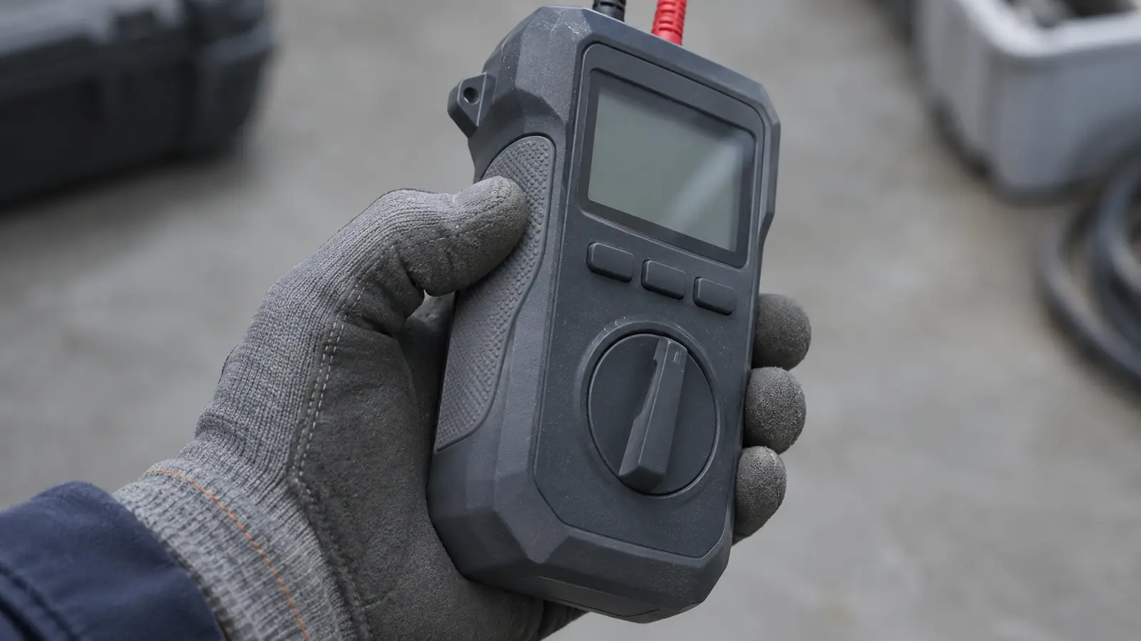
Both features could be added after the case is molded. Bringing either one into the mold changes how the part is made and what the finished case must pass in testing.
In both processes, hot plastic fills a shaped space in a tool called a mold. Meco’s guide to plastic injection molding explains how the plastic fills, cools, and comes out of the tool.
A practical comparison of overmolding vs insert molding starts with what goes into the mold and how the finished part could fail. Those details also help you compare a molded-in feature with a separate assembly step.
Key takeaways
- Start with function. A soft surface and a threaded mount solve different problems, even when they sit on the same part.
- Check soft-layer retention. Overmold retention can come from surface adhesion, the part’s shape, or both. Check the exact material grades and how the part will be used.
- Locate metal inserts. Insert molding usually relies on plastic locking around the insert’s outer shape. The mold must hold each insert in the specified position.
- Compare the full build. Tooling, placement, inspection, and saved assembly work all affect cost.
- Plan the sample check. Agree on the functional checks before comparing the first parts.
How does each process build the part?
Both processes form plastic against a part that already has a shape. The key detail is what that first piece does in the finished product.
How a soft layer takes shape
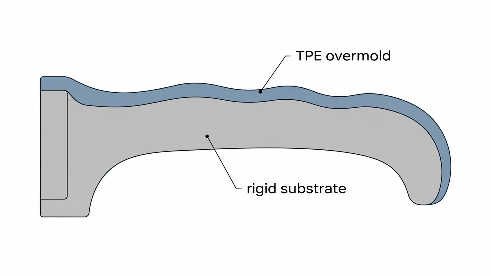
Imagine the hard shell of the test device. That shell is the substrate, or base part. The mold leaves an empty space along the sides where the grip will go. A second material fills that space and takes its final shape against the shell.
The soft material may be a thermoplastic elastomer, or TPE. A TPE can be shaped by heat and behaves like rubber in use. The layer formed on the shell is the overmold. The shell still gives the case its shape, while the overmold changes how it feels in the hand.
One way to make the part is to place a previously molded shell into a second mold. This is called pick-and-place overmolding. A two-shot setup forms the base and then adds the second material in one coordinated molding cycle. Meco’s 2K injection molding guide explains the machine setup for that route.
A general overmolding guide can explain the routes for building a part from two molded materials. Here, the next question is how a built-in metal feature changes the job.
How a metal feature becomes part of the case
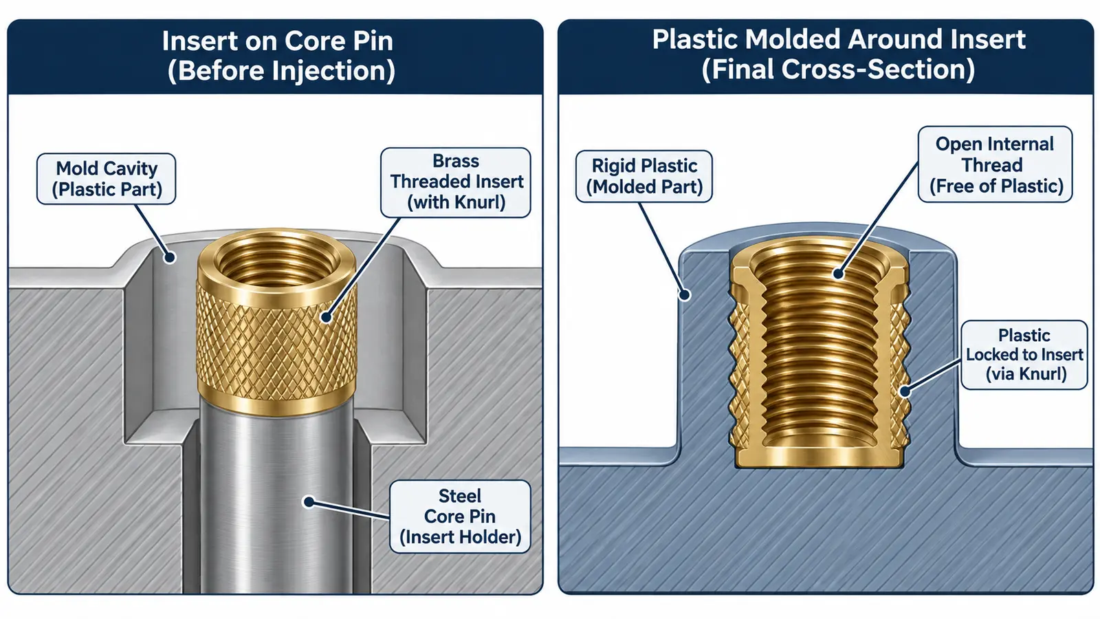
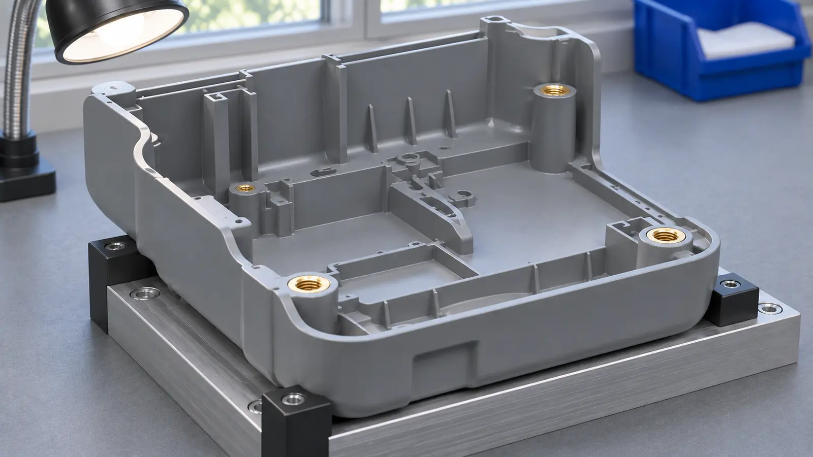
For the screw mount, a small brass piece with threads is made before the case is molded. That piece is the insert. It sits on a locator in the mold, a feature that sets its position and keeps the screw opening clear.
Hot plastic flows around the outside of the insert. When the plastic cools, it holds the metal in place, with the threads exposed for the screw. The body takes shape and captures the insert in the same molding step.
Suppliers sometimes use “overmolding” for any process that molds material over an existing piece. A shop may also describe a transferred plastic base as an insert. On a drawing or quote request, name the starting piece, the material added around it, and the surfaces that need to stay clear.
Overmolding vs insert molding at a glance
Compare the starting piece, the job of the added material, and the check that would show the design works.
| Question | Plastic over plastic | Plastic around a metal insert |
|---|---|---|
| What goes into the molding step? | A shaped plastic base, made in the same tool or placed in a second mold | A preformed metal piece, such as a threaded insert, sleeve, or pin |
| What does the part gain? | A surface that can grip, cushion, seal, or add a second color | A built-in feature that can take a screw, guide a moving part, or make an electrical connection |
| What keeps the materials together? | Adhesion at the contact surface, a physical lock, or both | Usually a physical lock as the plastic sets around the insert’s outer shape |
| What must the tool control? | Where the soft material starts and stops, and how the base is supported | The insert’s position and angle, plus the areas that must stay free of plastic |
| What should the first samples show? | A grip that stays attached in use, or a seal that passes its leak check | An insert that sits in the right place and stays fixed under the specified load |
The table gives a way to pick a route. The design review starts where the two materials meet. That is where the mold has to hold the part and where loads pass from one material to the other.
What has to stay attached and what has to stay in place?
For a grip, check how the edge stays down. For a threaded insert, check what keeps the metal from turning or pulling out.
Keeping a soft edge attached
Adhesion means the two materials stick where they touch. Some TPE grades are made to bond to certain hard plastics. Ask for the exact grade of each plastic, since two grades in the same family can bond differently. Teknor Apex’s explanation of TPE adhesion describes why the choice of both materials matters.
Shape can help hold the layer, too. A soft layer can wrap around an edge or flow through a hole and spread out on the far side. Once cool, the wider end acts like a small anchor. This is mechanical retention, which means the shapes lock together.
A long grip can look fine and still lift at a corner when a user catches the edge. Mark that edge on the drawing. The Avient overmolding part design guide explains how edge geometry and the area where the mold closes against the base affect the finished layer.
Keeping metal threads aligned
When a screw is tightened, it applies torque, or a twisting force. The insert must resist that twist. It may also see pull-out force, which acts along the screw’s length and tries to draw the insert out of the plastic.
The plastic around the insert carries these loads. Leave room for that plastic when laying out the housing. A threaded insert that fits the screw can still be a poor match for a narrow mounting post.
An insert may have a knurl, a raised pattern on its outer surface, or grooves that the plastic can fill. The molded plastic around these features helps hold the insert. The SPIROL molded-in insert guide shows how these inserts are placed on mold pins before plastic is injected.
Mark the thread and seating face that must remain clear. If the metal piece tilts or shifts while the mold fills, the screw may bind even when the insert is firmly held. A dedicated metal-insert design guide can cover insert geometry in greater depth.
Check the feature that matters. An insert can pass a position check and still turn during tightening. A grip can look smooth and still peel from the edge. Put the functional check on the same drawing or test plan as the visual check.
How should you choose for a real part?
Name the job of each feature and the failure you need to prevent. Then decide which features are worth building into the molding step.
Compare two jobs on one housing
On the test device, imagine that the side pads need to stay put after the case is wiped down and handled with gloves. That points toward a soft overmold. A useful trial would check how the edge holds after exposure to the intended cleaner and repeated handling.
On the back, the screw mount needs to keep the device fixed to its bracket after repeated removal. A molded-in threaded insert is a route to compare. Check the thread position and test for movement or damage after tightening and service cycles that represent the intended use.
When both features are needed, one possible build is to mold the shell around the insert, then mold the grip onto the shell. The second tool must locate the shell and keep the thread and seating face clear. Check those features again after the grip step.
Consider what could stay separate
A replaceable sleeve may suit a grip that wears out long before the device. A separate gasket may suit a cover that users open and reseal. For a screw mount, a threaded insert installed after molding can be worth quoting if the housing gives the installation tool enough room.
Compare how each route affects access, repair, and assembly work. Meco’s mechanical assembly guide explains where fastening and fit checks come into a build. That work belongs in the comparison if you decide to keep a feature separate.
Need a process review? Share the part drawing, the job of each feature, and your expected volume so Meco can review the molding and assembly options.
Get DFM Feedback on Your DesignWhat changes in tooling and part cost?
Compare the cost of a finished part that passes inspection. Tooling, handling, rejects, and the assembly work saved can all change the result.
Work done before and during molding
A transferred base needs a second tool, plus time to pick up, place, and check the base. A two-shot tool handles the transfer within the molding setup. That can reduce separate handling, while the tooling and machine setup can require more investment.
Insert molding adds the cost of the insert and the work of loading it. The supplier needs a way to seat it in the right direction and confirm that it is present. Parts with several inserts can take more handling or need automated loading, depending on the part and order volume.
Costs to put on the same quote
Ask each supplier to price the same design, quantities, and tests. A quote for molding alone may leave out the work needed to make the part ready for assembly.
- Tooling. Molds, any loading fixture, and the cost of design changes.
- Parts and handling. Base pieces or inserts, placement time, and any checks made before the mold closes.
- Inspection and rejected parts. Checks for the surface, fit, or load that the drawing calls for, plus the effect of scrapping a part with an insert already inside it.
- Assembly. Any separate fitting step the process removes, and any service or replacement step it adds.
Meco’s custom injection molding services support insert molding, overmolding, and two-shot molding. Its published planning ranges list 2 to 3 weeks for aluminum tooling and 4 to 8 weeks for steel tooling. Confirm the applicable lead time, design scope, and sample checks for the specific part with the supplier.
What should you check before ordering production parts?
Use trial parts to check the feature, the fit around it, and what happens after normal use. Agree on what counts as a pass before the trial.
For the grip, mark the edge most likely to lift and the areas that users press or rub. For a seal, agree on a leak test with the seal fitted as it will be in the product. Use the expected heat, cleaning, or wear conditions where they can change the result.
For an insert, check its location and angle against the drawing. Check that the correct screw starts and seats as intended. Agree on tests for torque or pull-out where the insert carries those loads, and use the screw and support conditions the design calls for.
Check fit again after the parts cool. The plastic can shrink as it cools, and the amount can vary across a part. On the test device, check how the finished housing sits on its bracket as well as where the insert sits in the housing.
Inspect the plastic around both features. Flash is a thin lip of extra plastic that can form where the mold closes. Near a thread or a sealing face, that extra plastic can block assembly or leave a gap. Meco’s injection molding defects guide explains flash and other common signs to record on first samples.
Share those test needs along with the drawing and expected quantities. Meco’s prototype-to-production guide describes how to carry the sample checks into a production plan.
Review your molded part
Share a drawing, expected volume, and the job of each molded feature. Meco can discuss how to make the part and what to check before a production order.
- Drawing review. Grip or seal edges, insert position, and assembly fit
- Material details. Base and soft material grades, or insert material and finish
- Quality documentation. First article inspection and material traceability as applicable
References and sources
- Teknor Apex. TPE Overmolding: Adhesion Explained.
- Avient. Overmolding: Part Design.
- SPIROL. Molded-In Inserts.
