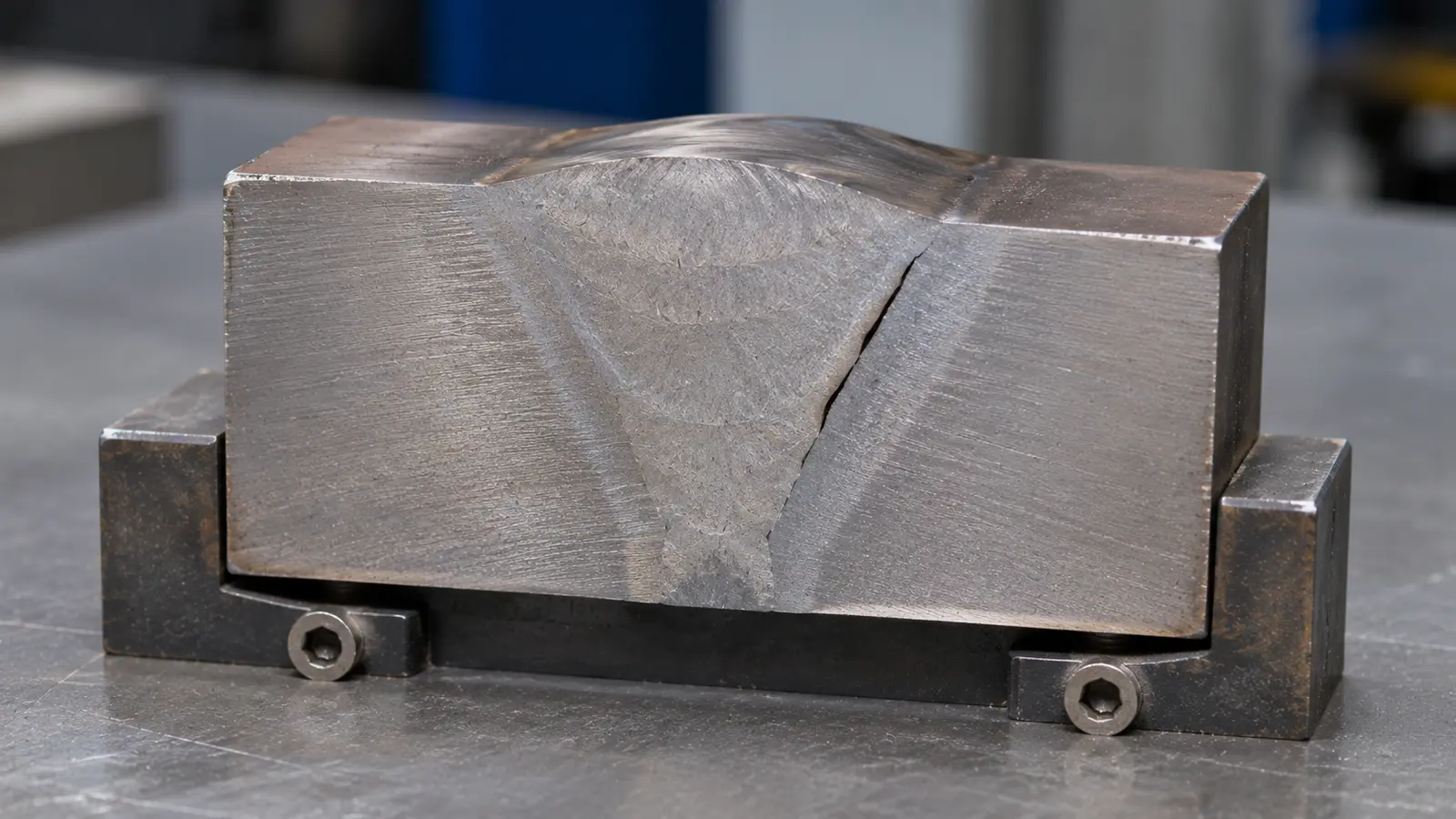
A weld can look complete yet have an area where the new metal did not bond to the metal beneath or beside it. That problem is called lack of fusion in welding. It can reduce the sound connection in a joint, even when the outside bead looks smooth.
If lack of fusion is suspected, do not judge the weld from a photograph alone. Check the joint drawing, welding conditions, and required acceptance rules. Use an inspection method suited to the flaw's likely position before deciding on repair.
A painted machine frame may have a neat weld along one corner. From the outside, the bead appears to join both pieces. But the weld could have melted and settled against one side without making a sound bond there.
This is why the shape of a bead and the strength of the connection are not the same question. An inspector may see the outside shape, while the critical unfused boundary stays inside the joint.
This article focuses on one welding defect. For the broader picture of surface and hidden flaws, see Meco's welding defects guide.
If you first need a comparison of welding methods, our types of welding article covers those processes separately.
Key takeaways
- Lack of fusion means the weld did not bond completely to the base metal or an earlier weld pass. It is not simply a rough bead.
- The flaw may lie at a joint sidewall, between deposited passes, or near the root. A smooth surface cannot rule it out.
- Incomplete penetration describes a weld that does not reach the specified root depth. It should not be used as another name for every fusion flaw.
- Limited access, poor cleaning, unsuitable parameters, or torch placement can keep the arc from melting the metal that must join.
- Inspection and repair must follow the actual drawing, material, welding procedure, and acceptance requirements.
What does lack of fusion mean in a welded joint?
Fusion means that metal at the joint melts and joins into one solid connection when it cools. In fusion welding, the base metal is the original part being joined. Filler metal, when used, adds material to the weld.
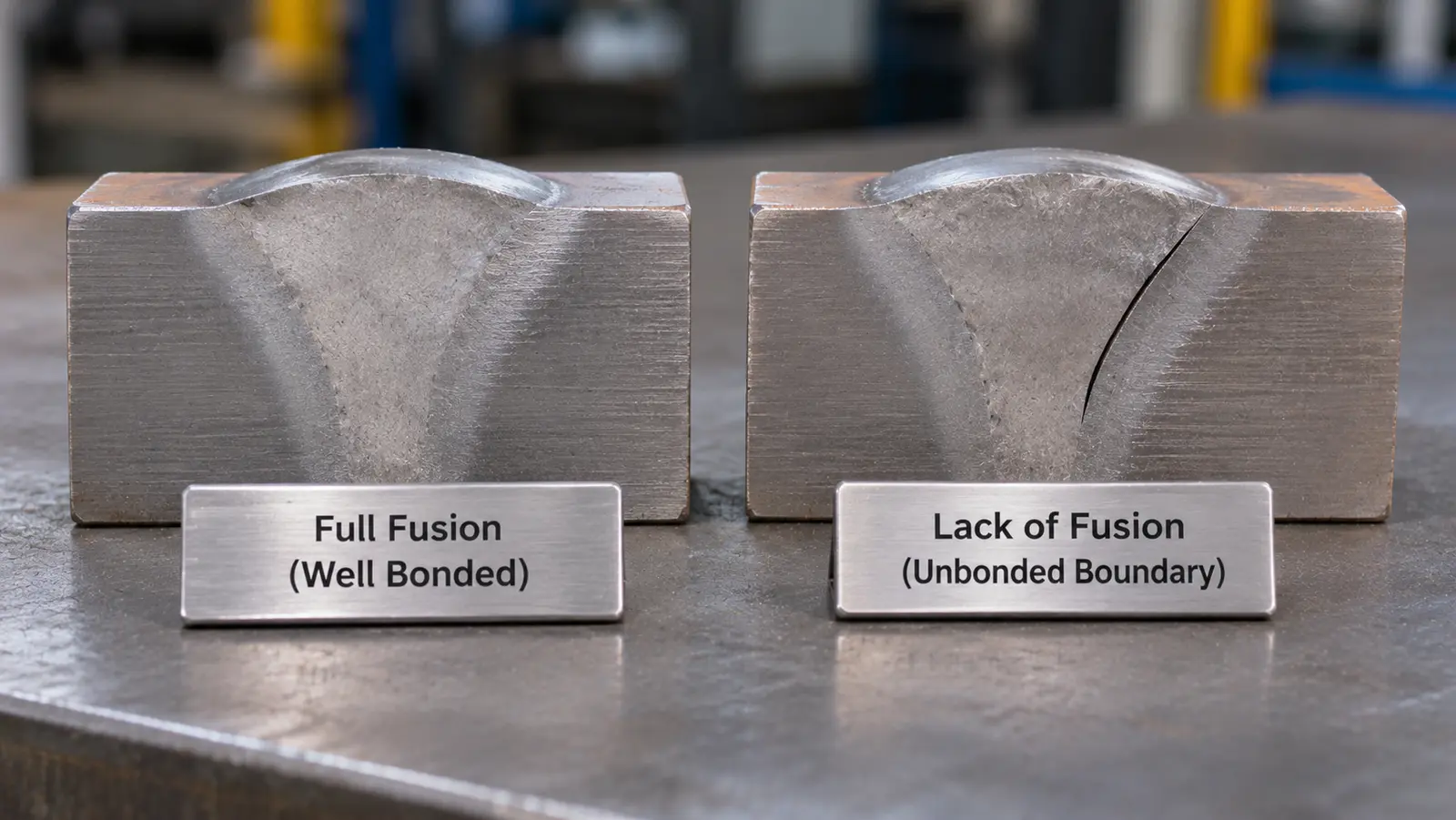
Lack of fusion happens when the deposited weld metal fails to join fully with a surface it was meant to melt into. The result can be a thin, unbonded boundary. The deposited metal may cover that boundary, so the finished bead does not always show an obvious opening.
That is different from weld porosity, where gas leaves cavities in the metal. A pore and an unfused boundary need different checks.
Where can lack of fusion occur?
The location matters because it helps a reviewer understand both the likely cause and the available inspection path. Weld metal can fail to join at more than one interface.
Sidewall fusion: the edge of the original metal
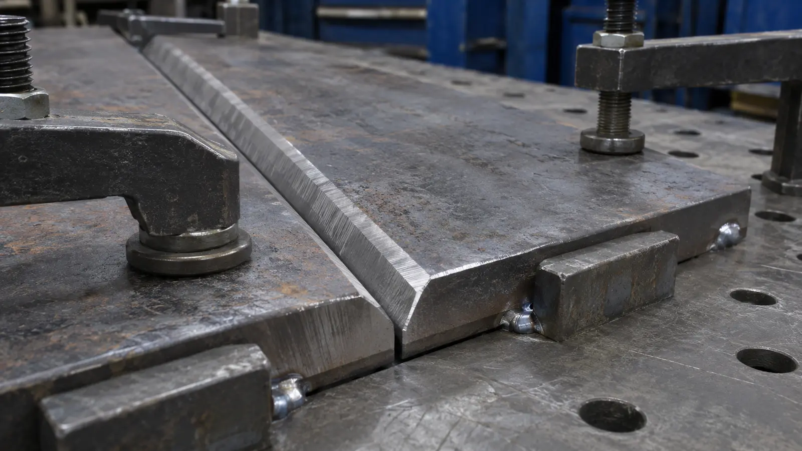
The sidewall is the prepared face of the base metal beside the weld. On a beveled butt joint, it is the sloping cut face. On a fillet weld, it is the surface of one member beside the bead.
If the arc melts the filler but does not melt enough of that face, a narrow unfused area may remain. This can happen when a joint is too narrow for good access or the torch points mainly toward the opposite side. The weld bead may still look full.
Inter-run fusion: between earlier and later passes
Thicker joints often need several weld passes. A pass is one deposited run of weld metal. Each new pass must bond to the exposed metal from the previous pass as well as to any base metal it reaches.
An uneven earlier bead can leave a pocket at its toe. Slag or heavy oxide left between passes may also block proper melting. A later pass can bridge over the pocket, hiding it under new weld metal. This is called inter-run, or interpass, lack of fusion.
Root fusion: the deepest part of the joint
The root is the deepest region of a joint, often where the prepared edges meet. Poor access or an unsuitable root opening can leave one face at the root unfused. Root fusion must be judged against the joint design: not every joint is intended to have full penetration.
Lack of fusion vs incomplete penetration: what is the difference?
These two terms are often mixed up because both can involve missing weld metal connection near the root. They describe different problems.
Lack of fusion means the weld metal has not bonded properly to an intended surface, such as a sidewall or an earlier pass. Incomplete penetration means the weld does not extend to the root depth required by the design. A joint can show one problem, the other, or both.
| Condition | What is missing? | Example of where it occurs | Main question for review |
|---|---|---|---|
| Lack of sidewall fusion | Bond between weld metal and prepared base-metal face | Along one bevel face in a multi-pass joint | Did the arc melt and join the intended sidewall? |
| Lack of inter-run fusion | Bond between separate weld passes | Between a root pass and a later fill pass | Was the earlier pass properly reached and fused? |
| Incomplete root penetration | Weld metal reaching the specified root depth | At the bottom of a butt joint | Was full or stated partial penetration required? |
A partial-penetration weld is not automatically defective. Some drawings deliberately specify it. The problem is failing to make the connection that the approved design requires. TWI treats incomplete root penetration and sidewall or inter-run fusion as related but distinct imperfections.
Meco's weld undercut guide addresses a different surface problem: a groove beside the weld toe. That groove is not evidence, by itself, that the metal underneath failed to fuse.
Why can an unfused area affect weld performance?
A joint carries force through the metal that is actually connected. An unfused region reduces the effective bonded area, but the effect is not identical for every part. The location and shape of the flaw matter, along with how the part is used.
Consider a welded mounting bracket on an industrial conveyor. The bracket may carry a mostly steady load. Another bracket may see repeated vibration as the machine runs. A flat unfused boundary can act as a place where stress is concentrated, especially under repeated loading.
Fatigue is damage that builds under repeated loads. A crack may start at a weak point and grow over many cycles. That does not mean every suspected fusion flaw will cause a crack. It means the reviewer needs the real loading conditions, not just a close-up photograph.
What causes lack of fusion in welding?
Most causes have one thing in common: the intended joining surface did not receive the right combination of heat, access, and cleaning. This does not mean the solution is simply to turn the current up.
Joint design and restricted access
A narrow groove may keep the electrode or torch from aiming into the sidewall. In gas metal arc welding (GMAW, often called MIG), the nozzle also needs room. A large nozzle in a tight joint can force a poor working angle.
For MIG work, Meco's gas shielded welding page explains the process equipment. A fusion diagnosis still depends on the exact joint and qualified setup.
Welding settings and travel conditions
Current affects the heat available from the arc, while voltage and arc length influence arc behavior and weld shape. Travel speed changes how long heat acts on the joint. The balance also depends on the process, material, filler, position, and joint size.
Too little effective heat at the sidewall can leave it unmelted. But excessive deposition or a very large molten pool can also run ahead of the arc and cover a surface before that surface fuses. TWI describes this as weld-pool flooding.
Torch direction and bead placement
The torch or electrode must direct heat toward the metal that needs to join. If its angle favors one side, the other side may remain partly unfused. In a multi-pass weld, poor bead placement can leave a recess that later metal covers rather than melts.
A controlled weave, which means moving the arc slightly across the joint, can help reach the sidewall on some procedures. It is not suitable for every weld. The approved heat-input limits and the qualified technique still govern its use.
Oxides, slag, and other material at the interface
Scale, heavy oxide, oil, or slag can stop the new pass from making a sound bond. Slag is the solid residue made by some welding processes and must be removed where the procedure requires it before another pass is deposited.
TWI also identifies magnetic arc blow as a possible cause in some ferromagnetic-steel arc welding. This is when magnetic forces push the arc away from the intended path. It should be investigated when the observed arc behavior supports that concern, not assumed for every fusion flaw.
How can you trace the likely cause on a real part?
A useful investigation starts with a pattern, not with a preferred fix. Where is the suspected boundary? Is it on one sidewall, between passes, or at the root? Did the problem appear after a change to the joint or the process?
| Observation | First checks | What the observation does not prove |
|---|---|---|
| Indications repeat on one side of a groove | Torch angle, groove width, access, and bead placement | That the machine current is always too low |
| Indications appear between weld passes | Cleaning, prior-pass shape, and the next pass location | That the original base metal is defective |
| Problems begin after a fixture change | Torch clearance, part position, and joint fit | That the filler metal must be changed |
| Problems follow a new procedure or operator setup | Qualified settings, technique, and process records | That one setting alone caused the problem |
| Only a finished exterior photo is available | Drawing, weld location, service duty, and inspection plan | That internal fusion has been verified |
Imagine a batch of fabricated steel supports. A qualified inspection reports repeated indications beside one bevel face after the frame fixture is changed. The team compares the new torch clearance and joint preparation with the previous approved setup.
Suspect a hidden fusion problem? Share the drawing, joint geometry, material and inspection requirements. Meco can review manufacturing conditions and discuss a suitable quality plan.
Talk to an EngineerHow is lack of fusion detected when the weld looks sound?
What visual inspection can and cannot tell you
Visual testing (VT) checks features that can be seen with appropriate access and lighting. It can identify a poor weld profile, missed weld area, surface opening, or unusual bead placement that deserves investigation.
However, a smooth and continuous bead is not proof of complete fusion beneath it. Visual testing cannot reliably confirm a buried unfused plane. A surface photo should be treated as a clue, not as an internal inspection result.
When surface and internal methods may help
Liquid penetrant testing (PT) can show certain surface-breaking openings on suitable nonporous materials. Magnetic particle testing (MT) can find certain surface and near-surface discontinuities in ferromagnetic materials, such as many carbon steels. Neither technique proves the whole interior is bonded.
Ultrasonic testing (UT) sends sound into metal and analyzes returned signals. It can be effective for some planar lack-of-fusion indications when the technique and access are appropriate. Radiographic testing (RT) uses penetrating radiation to make an image. RT can reveal some fusion flaws but may miss a narrow planar flaw depending on its orientation.
TWI notes that UT is often more effective than RT for inter-run lack of fusion, while also warning that material and testing conditions affect results. The practical decision belongs to a qualified NDT team, not a fixed ranking of methods.
Read the result against the agreed acceptance criteria
A reported indication is not automatically a final rejection. Reviewers need the drawing, applicable code, weld procedure, test method, and report. Material thickness, joint geometry, access, and the expected load can all influence the inspection plan.
This Cluster concentrates on why an unfused interface can be difficult to find, rather than comparing every nondestructive test.
How can manufacturers prevent repeat fusion problems?
Prevention should target the missing bond rather than only improve the outside appearance. It begins before welding, continues through each pass, and ends with evidence from the actual production setup.
Make the intended joining surface reachable
Review the groove angle, root opening, part position, and fixture clearance for the selected process. Check whether the nozzle or electrode can reach the required sidewalls without an awkward angle. A drawing that looks accessible on screen may be harder to weld inside a real assembly.
This is part of the broader custom fabrication and welding planning process. Cutting, forming, fixturing, welding, and later assembly should be considered together, not as isolated tasks.
Control preparation and the sequence of passes
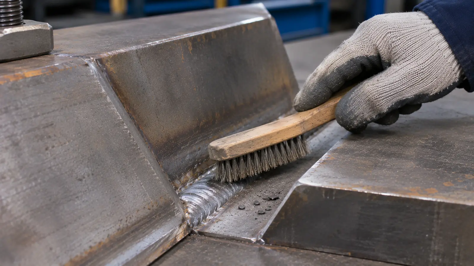
Prepare the base metal as specified, and clean each deposited pass when required before covering it. Check the toe shape of earlier passes and ensure the next run can reach both the previous metal and the intended sidewall.
Prove that the revised process works
After a change, inspect a first-off or test weld made with the intended material, fixture, joint, and procedure. If the project requires internal examination, a better-looking bead is not enough. Record what changed and what the agreed inspection showed.
Meco's R&D engineering support includes design and production planning. Early review may keep a joint from becoming hard to weld or inspect after assembly.
For joined sheet components, our sheet metal assembly guide covers how fit and joining order affect the final part.
What happens if lack of fusion is found after welding?
Do not hide the indication with grinding, extra filler, or surface finishing before a qualified reviewer decides what it means. Covering a suspected unfused boundary does not make the missing bond disappear.
First, identify and hold the affected part or lot as required. Keep the weld location, procedure, material, inspection report, and relevant production records together. Next, compare the finding with the drawing and applicable acceptance requirements.
If repair is authorized, the approved repair plan may call for controlled removal of the unsound weld region followed by rewelding and reinspection. TWI describes localized removal and rewelding as a common remedy, but the repair method must be suitable for the actual joint and project.
A repair may alter fit around nearby parts. Meco's mechanical assembly guide explains why the completed product must be considered.
What should you send for an engineering review?
Start with a marked joint drawing, material grade, thickness, weld type, welding position, and quantity. Include the welding method, available procedure reference, and the acceptance criteria the joint must meet.
Add the inspection report with the indication location and test method. Note when the concern first appeared and whether joint preparation, a fixture, or any process settings changed. These facts let an engineer plan the next check instead of guessing from a photograph.
Meco works under an IATF 16949:2016 certified quality system. That supports controlled production and documentation, but it is not a substitute for the weld's applicable code or a claim that every weld has passed a particular test.
Plan a Verifiable Welded Part
Share the drawing, joint geometry, material, quantity, and any suspected fusion or inspection concern. Meco can discuss manufacturability, weld access, and a practical review plan.
- Part details. grade, thickness, drawings, and production quantity
- Joint details. weld type, fit-up, access, and expected loads
- Quality needs. applicable code, inspection scope, and acceptance criteria
- Evidence. marked photos, reports, and process-change notes
