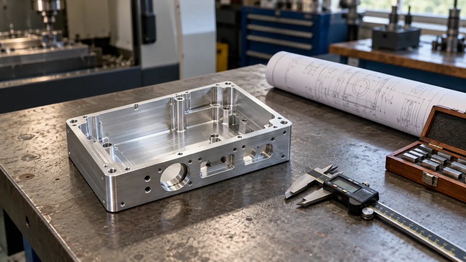
CNC machining tolerances set the acceptable dimensional variation on a finished part. Choose the widest range that still meets the feature's function, assembly and quality needs.
Use ISO 2768-1 for suitable general dimensions, then give close limits to important fits. Confirm each critical tolerance against the chosen process and inspection method.
The best CNC machining tolerance is the loosest one that lets a part work and assemble correctly. A tight number has value only when it protects fit, sealing, alignment or performance.
This guide explains the ISO 2768 classes, typical machining limits and the cost of precision. It also separates dimensional tolerance from surface roughness and geometric controls.
Three comparison tables help you check general drawing limits, process capabilities and Ra values. Use them as starting points, then confirm what the actual setup can hold.
At the end, the FACT check gives you four questions to use before requesting a machining quote.
Key takeaways
- Start with function. Tighten only features that matter to fit, sealing, location or movement.
- Use ISO 2768-1 correctly. General limits depend on feature size and the selected class.
- Match process to tolerance. The same number can be easy on one setup and expensive on another.
- Keep size and finish separate. Dimensional tolerance, Ra and GD&T describe different requirements.
- Plan inspection. If a critical tolerance cannot be measured, it cannot be reliably accepted.
What Does CNC Machining Tolerance Actually Mean?
A CNC machining tolerance is the permitted variation from a drawing dimension. It defines the acceptable limits, not a promise that every part will be exactly nominal.
No machine cuts perfectly. Even two parts machined one after the other can measure slightly differently because tools, fixtures and temperature vary.
If a hole is specified as 10.00 ±0.05 mm, its acceptable size runs from 9.95 to 10.05 mm. Anything outside that range fails the dimensional requirement.
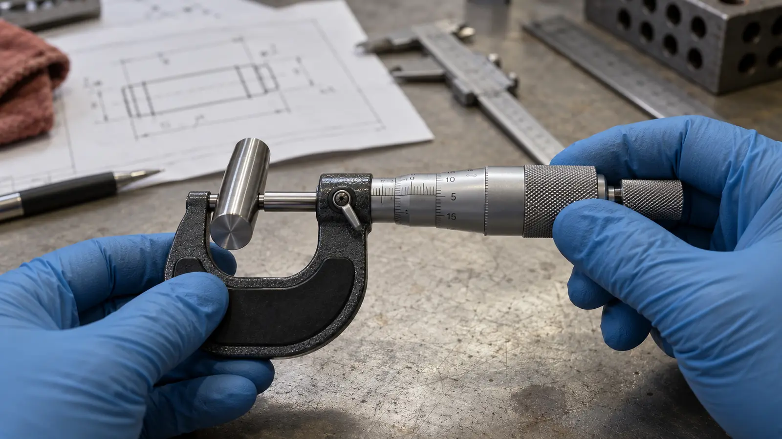
Tolerance and accuracy are related, but not the same. Tolerance is the allowed range on the drawing. Accuracy describes how close a process comes to its target value.
Do not apply the tightest tolerance everywhere. Put close limits on the features that mate, seal, locate or rotate. Give noncritical faces a suitable general tolerance.
For examples of how material choice affects manufacturing, see Meco's best materials for CNC machining guide.
What Is ISO 2768 and What Do f, m, c, and v Mean?
ISO 2768-1 gives general tolerances for linear and angular dimensions without an individual tolerance callout. Its four linear classes are fine (f), medium (m), coarse (c) and very coarse (v).
Instead of adding the same limit to dozens of dimensions, an engineer can use a drawing note such as General tolerances: ISO 2768-1, class m. The permitted variation then depends on the dimension's size and class.
The ISO 2768-1:1989 standard still lists these four classes. The following chart shows a selected set of linear dimensions.
| Nominal size range (mm) | f (fine) | m (medium) | c (coarse) | v (very coarse) |
|---|---|---|---|---|
| 0.5 up to 3 | ±0.05 | ±0.1 | ±0.2 | Not specified |
| over 3 up to 6 | ±0.05 | ±0.1 | ±0.3 | ±0.5 |
| over 6 up to 30 | ±0.1 | ±0.2 | ±0.5 | ±1.0 |
| over 30 up to 120 | ±0.15 | ±0.3 | ±0.8 | ±1.5 |
| over 120 up to 400 | ±0.2 | ±0.5 | ±1.2 | ±2.5 |
| over 400 up to 1000 | ±0.3 | ±0.8 | ±2.0 | ±4.0 |
A 5 mm dimension in class m allows ±0.1 mm, while a 300 mm dimension in the same class allows ±0.5 mm. A larger nominal dimension has a larger specified range.
Important standards update: ISO 2768-2:1989, which covered general geometric tolerances in classes H, K and L, has been withdrawn and replaced by ISO 22081:2021. Do not add a new ISO 2768-2 callout without confirming the applicable customer drawing and standards revision.
How to use the chart
Use a general class only for dimensions that lack their own limits. Keep explicit tolerances for functional fits and inspect them to the drawing requirements. Medium (m) is common, but it is not the right default for every product.
What Tolerance Can Each CNC Process Hold?
CNC turning, milling, drilling, reaming and grinding do not have one shared tolerance limit. Each process responds differently to part geometry, tools, fixtures and measuring conditions.
For example, a supported shaft on a lathe may be easier to control than the bottom of a deep milled pocket. These are typical planning ranges for controlled operations, not guaranteed shop or machine specifications.
| CNC operation | Typical achievable tolerance | Best for |
|---|---|---|
| CNC turning (lathe) | ±0.025 mm (±0.001 in) | Round shafts, pins, fittings |
| CNC milling (3-axis) | ±0.025 to ±0.05 mm | Brackets, plates, housings |
| CNC drilling | ±0.05 to ±0.1 mm | Clearance and bolt holes |
| Reaming / boring | ±0.01 mm | Precise bores and bearing seats |
| 5-axis milling | ±0.01 mm or tighter | Complex curved or angled parts |
| Grinding / lapping | ±0.005 mm or better | Gauge surfaces, ultra-precision |
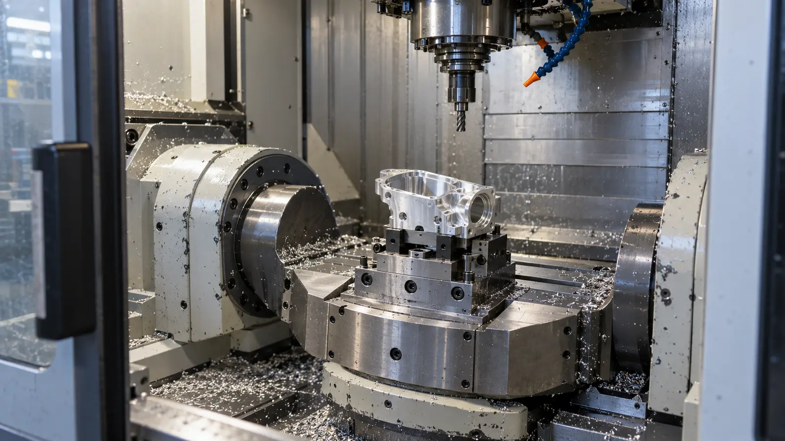
When do you really need ±0.01 mm machining?
A ±0.01 mm tolerance is often reserved for critical fits such as a bearing seat, locating bore, sealing interface or sensor mount. On a nonfunctional outside edge, that same tolerance usually creates extra work without improving the assembly.
For difficult angled features, 5-axis CNC machining can reduce setups and improve tool access. Meco reports capability down to 0.005 mm on selected key features, but the part drawing, setup and inspection plan still decide what can be quoted.
To turn these tolerances into a manufacturable drawing, Meco's CNC engineering services can support process selection and design review.
Why Do Tighter Tolerances Cost More?
Tighter limits raise machining cost when they require slower cuts, special fixtures, extra passes, repeated inspection or more rejected parts.
The cost change is not a fixed multiplier. It grows sharply once a dimension moves beyond what the chosen setup can hold reliably.
In a published example, Modus Advanced estimates that moving from rough to precision machining can raise costs about fourfold, while some ultra-precision cases may reach 24 times a standard rate. These are illustrative cases, not a general quotation or rule.
Thermal growth adds another risk. A 300 mm aluminum part can change length by about 0.07 mm across a 10°C temperature shift, depending on the alloy. Measurement temperature matters when the drawing tolerance is smaller than the possible thermal change.
Check the cost before tightening
Compare the proposed tolerance with the feature's fit or sealing need. If tightening from ±0.13 mm to ±0.025 mm adds special inspection or finishing, confirm that the improved function justifies the extra work.
For a broader view of programming, setup and machining charges, read Meco's CNC machining cost guide.
How Does Surface Roughness (Ra) Fit In?
Dimensional tolerance controls acceptable size. Surface roughness Ra describes the average absolute deviation of a measured surface profile, so it controls a different part of quality.
A diameter can meet its dimensional limits and still be too rough for a seal. A polished surface can also have the wrong diameter. The two requirements must be set and checked separately.
Ra is usually stated in micrometres (µm). Lower Ra values mean a smoother measured profile. The examples below show common targets and processes, but actual results depend on tool condition, feed, material and the finishing method.
| Ra (µm) | Ra (µin) | Typical process | Where it's used |
|---|---|---|---|
| 6.3 | 250 | Rough milling, turning | Non-contact, clearance faces |
| 3.2 | 125 | Standard milling / turning | Brackets, general surfaces |
| 1.6 | 63 | Fine milling, wire EDM | O-ring grooves, press fits |
| 0.8 | 32 | Fine turning, grinding | High-pressure seals |
| 0.4 | 16 | Grinding, honing | Bearings, sliding surfaces |
| 0.1 | 4 | Lapping, superfinishing | Gauges, optical seats |
Do not specify a very low Ra value on hidden or noncontact surfaces unless the function calls for it. For seals, sliding faces and coating-critical areas, show the required surface condition on the drawing.
See Meco's surface finish chart for Ra comparisons. The surface finishing services page covers available post-machining treatments.
Are your tolerances adding cost? Send the drawing, material and quantity. Meco can review critical features, inspection needs and practical machining options before quoting.
Discuss Your CNC ProjectWhen Should You Use GD&T Instead of Plus/Minus Tolerances?
Use geometric dimensioning and tolerancing (GD&T) when form, orientation or location relative to datums matters as much as a feature’s size.
Plus/minus limits work well for lengths, diameters and basic dimensions. They may not explain how flat a mounting face must be or how a hole pattern must line up with another component.
ASME Y14.5-2018 provides a standard drawing language for GD&T. A position tolerance, for example, can define the allowable location of a hole axis relative to selected datum features.
GD&T helps control tolerance stack-up, where small variations across separate parts add together and affect final fit. Applied well, it can make assembly requirements clearer without forcing unnecessary limits on every independent dimension.
When GD&T adds value
Use it for bolt patterns, seals, rotating features, flat mounting faces or assemblies that depend on alignment. A simple stand-alone bracket length may need only a plus/minus limit. The choice depends on design intent.
Datums and functional tolerances are best reviewed before production. Meco's R&D engineering team can support early design and verification planning.
The 5 Most Common Over-Tolerancing Mistakes
The most expensive tolerance mistakes come from specifying precision without tying it to a functional or inspection requirement.
Use this drawing checklist before releasing a part for quotation:
- Tightening every dimension. Reserve close limits for mating, locating, rotating and sealing features. Use the chosen general tolerance elsewhere.
- Calling out low Ra everywhere. Match surface finish to friction, appearance, coating or sealing needs.
- Ignoring thermal movement. Think about part size, material expansion and inspection temperature.
- Accepting default CAD callouts. Check that each tolerance was selected for a reason.
- Skipping a design for manufacturing (DFM) review. Discuss features that may need a different machine, fixture or inspection method.
A DFM review can find ways to reduce cost without changing the fit or function. Meco's internal guidance cites typical savings of 15 to 30% from suitable design improvements; project results vary.
How to Choose the Right Tolerance: The FACT Check
The FACT check reviews each critical feature for Function, Assembly, Cost and Test. It makes tolerance decisions easier to explain and verify.
Before sending a drawing for production, walk through these four questions. They expose limits that are too tight, too loose or difficult to inspect.
F: Function
Does the dimension determine how the part works? A sealing land, bearing seat or locating face may need close control. A clearance edge often does not.
A: Assembly
Does it contact or align with another part? Evaluate the full stack of dimensions. Consider whether a datum and geometric callout would explain the fit more clearly.
C: Cost
What does the tighter requirement buy you? Ask which process, setup or inspection step will change, and whether the function improves enough to justify that cost.
T: Test
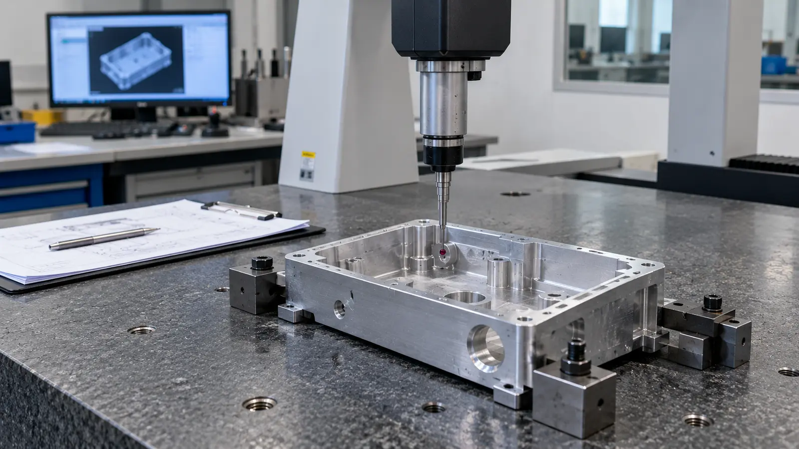
Can you measure the feature reliably? Critical dimensions need a practical measurement method, gauge plan and acceptance rule. Meco uses coordinate measuring machine (CMM) inspection and can support FAI and PPAP documentation where required.
Run critical features through FACT, then apply a suitable ISO 2768-1 class to the dimensions that do not need separate limits. Meco can review drawings for custom CNC machining before the design enters production.
Review Your Machining Tolerances
Share your drawing and quantity. Meco can review functional features, suggest practical limits and plan how critical dimensions will be checked.
- DFM feedback. On the features that drive cost.
- 24-hour quote target. With the needed technical inputs.
- Precision machining. CNC milling, turning and 5-axis options.
- Quality systems. IATF 16949:2016 certification and inspection records.
- Production range. Prototypes through repeat orders.
References and sources
- International Organization for Standardization: ISO 2768-1:1989, general tolerances for linear and angular dimensions.
- International Organization for Standardization: ISO 22081:2021, general geometrical and size specifications; replaces ISO 2768-2.
- The American Society of Mechanical Engineers: ASME Y14.5-2018 (R2024), dimensioning and tolerancing.
- Modus Advanced: The Hidden Cost of Tight Tolerance, illustrative comparisons of machining costs.
Tolerance values are selected examples. Follow the applicable drawing, customer requirements and standard editions for acceptance.
