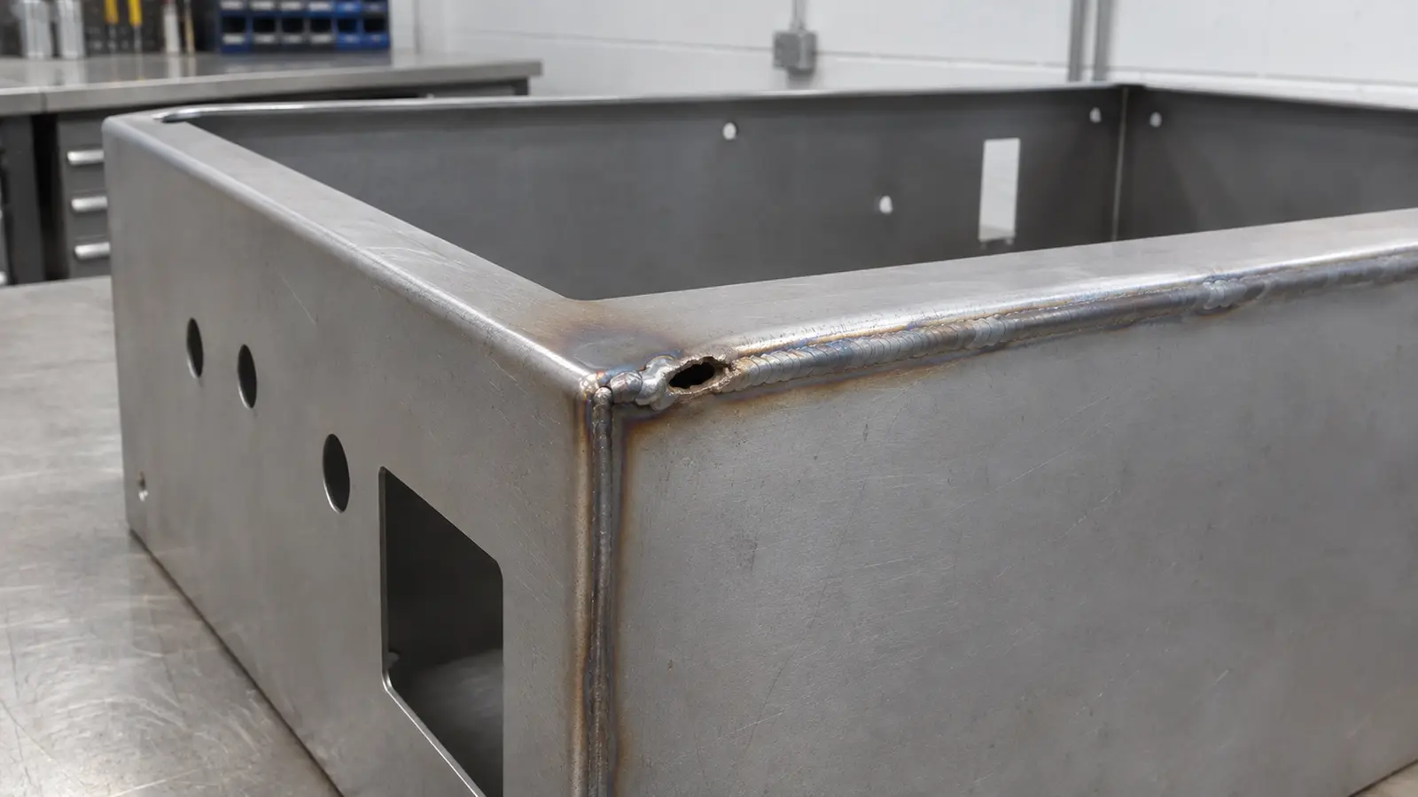
A burn-through hole is a sign that the weld pool lost support and melted through the joint. On thin metal, it can happen when too much heat stays in one spot or when an open gap leaves too little metal to bridge. Do not assume the only fix is lowering current.
Check the hole location, sheet thickness, joint fit and welding record first. Then compare changes to the approved settings, fit-up, backing and fixtures, and verify a corrected sample before restarting production.
A thin steel cover may look easy to weld because the seam is short. Yet one small opening along its edge can turn a usable part into a rework decision. The rest of the seam may appear continuous, which makes it tempting to blame a single moment of poor technique.
That reaction can miss the real reason. A widened joint gap, a slightly different formed edge, or a heat setting carried over from thicker material may change how the molten metal behaves. The same process can therefore work on one batch and burn through another.
This article deals with one specific weld defect. The Meco welding defects overview explains other defects and inspection limits. For the main differences among joining processes, see the types of welding guide.
Key takeaways
- Burn-through is a hole formed when the molten weld pool collapses or melts through the metal. It is not the same as normal full penetration.
- Thin sheet and open joint gaps leave less metal to support the pool, so fit-up can matter as much as a machine setting.
- Reducing local heat exposure, correcting gaps, using suitable backing, and holding the part consistently are different controls with different uses.
- A hole can be visible, but inspection still needs the drawing, joint purpose, and acceptance rules. Do not hide the evidence under a new bead.
- A first-off test should show sound welding and correct part dimensions, not just the absence of a visible hole.
What happens when a weld burns through thin metal?
In fusion welding, heat melts the edges of the parts and may also melt filler metal. The liquid area is called the weld pool. It must remain supported long enough to solidify and make the intended joint. Burn-through occurs when that pool loses support and opens a hole through the work.
Imagine two thin steel panels joined at a corner. The arc heats the edge, but the edge has limited metal around it to absorb energy. If liquid metal falls away or the opening becomes too wide to bridge, a hole remains. The surrounding edge may look rounded or irregular because it has melted back.
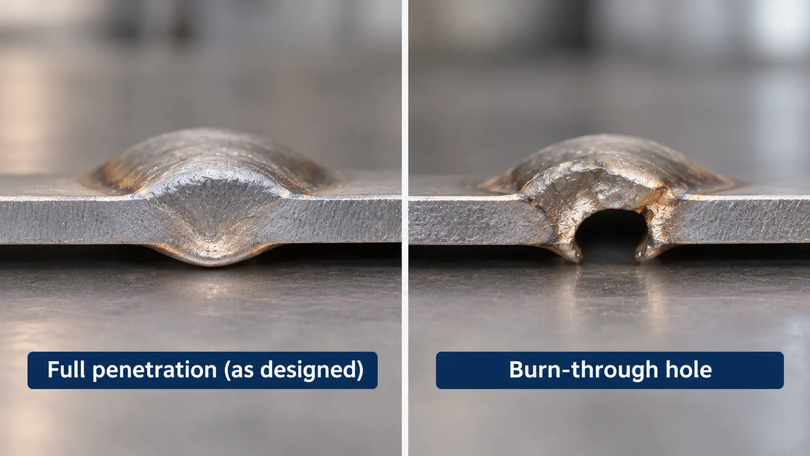
A small amount of weld metal appearing on the underside is not automatically burn-through. Some joints are designed for complete penetration, meaning the weld reaches through the required depth. Burn-through is the unwanted loss of material and support, not simply seeing a root bead from the back.
This distinction matters during inspection. A shiny underside bead can be acceptable under the approved design. An unintended opening that removes metal requires evaluation, even if filler appears nearby.
Why is thin sheet more likely to burn through?
Thin sheet has less metal around the weld to spread heat. It also has less thickness to support the liquid pool. Heat and joint shape therefore have a stronger local effect than they would on a thick steel plate. This is one reason a welding setup that works on a bracket may be unsuitable for a light-gauge enclosure.
Metal grade and thermal behavior also matter. Aluminum can carry heat away quickly yet need careful control of the pool, while stainless steel retains heat differently and can distort near a seam. A single current value cannot represent all materials, thicknesses, or welding positions.
Sheet thickness is only part of the question. A formed flange may be thinner at an overworked corner, or grinding may remove edge material before welding. A wide root gap leaves empty space under the pool. The pool then has fewer solid edges supporting it, making collapse more likely.
Meco’s sheet metal basics article explains how thickness, grades and applications differ. Here, the issue is how those choices affect one welded joint.
What does burn-through look like on a finished part?
The clearest sign is a hole or melted opening through the base metal or welded joint. Its size may vary. Some holes have irregular rims with metal pulled away from the edge. Others occur in a line where the gap changes along a seam. A photograph can document the opening, but it cannot establish every underlying cause.
It helps to compare the front and back of the joint. On the back, a normal root bead may be visible. Where burn-through has occurred, the intended joint is interrupted by missing metal. Around a thin flange, the gap may also have widened because the edge melted back.
Check nearby holes, cutouts, bends and tack welds. A defect that repeats beside a cutout may point to local geometry or reduced edge support. One that repeats where two sheets separate may indicate fit-up or clamp access. Those patterns are clues, not a diagnosis.
| OBSERVED FEATURE | POSSIBLE MEANING | WHAT TO CHECK |
|---|---|---|
| Open hole through joint | Possible burn-through with missing metal | Hole position, size, edge condition and joint requirements |
| Smooth metal on underside | May be intentional penetration | Approved drawing and weld specification |
| Hole starts at wide seam gap | Pool may have lost edge support | Fit-up measurements and fixture location |
| Burn-through near a cutout | Local heat and edge shape may matter | Cutout distance, thickness and weld position |
Burn-through must also be distinguished from porosity. Porosity is made by gas pockets trapped in solid weld metal; a visible pore can be small and round. Burn-through involves the loss of the supported pool and can leave a much larger through-opening. The Meco weld porosity article discusses gas-related cavities separately.
What usually causes burn-through during welding?
The immediate event is loss of pool support, but several conditions may lead to it. The useful question is not only whether the arc was hot. It is why the metal at that particular location could not remain in place long enough to form the joint.
Too much effective heat at one location
Welding current and voltage influence arc conditions, while travel speed affects how long heat stays near the same place. A slow travel speed can allow heat to build in a small section of sheet. An unsuitable combination of settings, filler and technique can make the pool too large for the edge to support.
Do not infer that every burn-through hole needs a lower current setting. A change that makes the pool smaller could also leave an unfused joint if taken too far. The setting needs to remain within a qualified welding procedure and still make a sound weld.
A joint gap that is too wide or uneven
Two panels may meet at one end but separate at the other because of cutting, bending or clamping variation. In a wide gap, the weld must bridge open space. The molten metal has less support, and the operator may stay in the area longer to fill the opening. Both factors can increase burn-through risk.
Before changing the arc, compare the real fit-up with the drawing and the last accepted setup. A gap problem should not be disguised with extra filler or more heat. It is often more repeatable to correct how the parts meet.
An unsupported edge or local loss of thickness
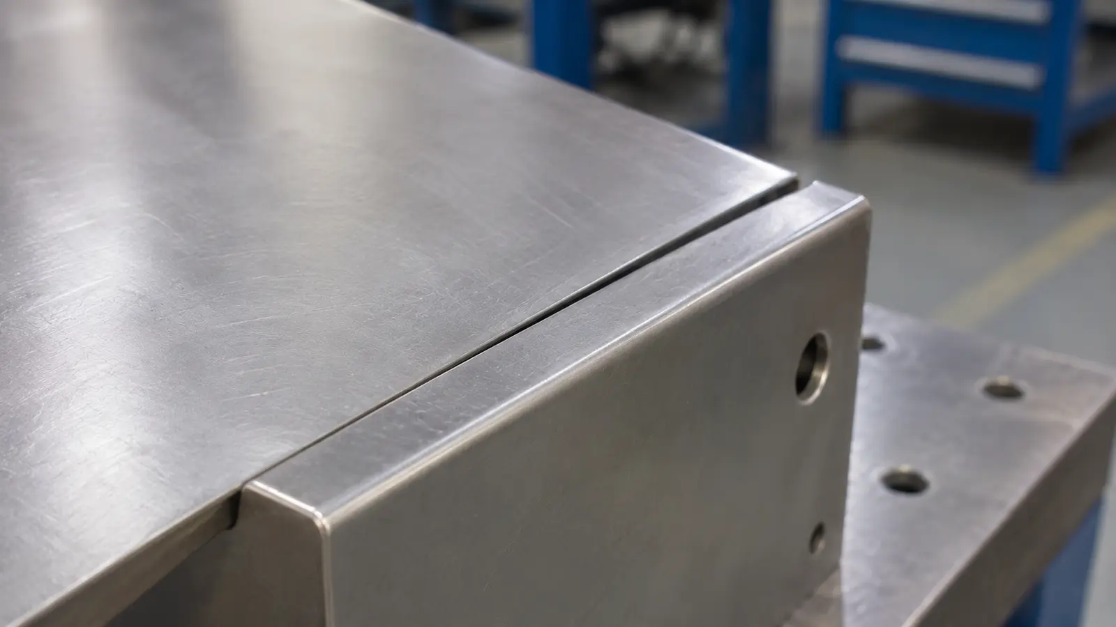
Outside corners, free edges and cutout borders can be more sensitive because there is less nearby metal. A thin root face or edge worn away by grinding gives the pool less support. This is a joint preparation issue as well as a welding issue.
For instance, a ventilation opening close to a seam can leave a narrow strip between the cutout and the weld. If that strip heats quickly, its behavior will differ from the broad flat area beside it. A designer should check whether the weld is placed too near a vulnerable edge.
Technique, position and sequence
Torch angle, arc length, bead size, travel consistency and welding position all affect how liquid metal is directed. Gravity may make the pool harder to support in some positions. A series of long welds can also raise the temperature of nearby material before a later section is joined.
These are linked factors. A shift in operator position may make the arc dwell at an already open gap; changing only one number on the machine may not solve that combined problem. For method-specific background, Meco’s TIG welding service page explains the process without serving as a universal settings chart.
How can a team trace the main cause without guessing?
Start by marking where the hole formed. Compare that spot with the seam gap, actual thickness, tack locations, clamping points and weld travel path. Review what changed between accepted parts and the affected batch. Do not jump straight from the hole to a preferred adjustment.
Consider a hypothetical batch of folded sheet-metal housings. An opening appears repeatedly near the same rear corner, where a narrow flange meets a side wall. The team checks whether the bending operation changed the corner gap or whether a fixture stop is no longer supporting the flange. Only then does it review the weld schedule and arc conditions.
This is a hypothetical example, not a reported Meco project. It shows why repeated defect location may help separate a geometry problem from an equipment-wide one.
| PATTERN | FIRST CHECKS | DOES NOT PROVE |
|---|---|---|
| Hole occurs where gap grows | Part dimensions, edge preparation, fit-up and clamping | That current alone is too high |
| Only one corner burns through | Edge support, position, nearby openings and heat history | That the base material is defective |
| Problems start after process change | Approved settings, filler, travel speed and test records | That every part needs extra backing |
| Holes repeat after a new fixture | Fixture contact, joint alignment, tack position and clearance | That the operator alone caused the fault |
| Hole present but underside bead looks sound elsewhere | Drawing, weld continuity and acceptance criteria | That all other joints are acceptable |
Record the part number, drawing revision, sheet grade, thickness, joint location, process, fixture revision and available inspection photographs. A short test using the same joint geometry is more useful than a good-looking bead made on unrelated scrap.
Burn-through in thin metal? Share the drawing, sheet thickness, joint gap and inspection concern. Meco can discuss manufacturability and a practical quality review.
Talk to an EngineerWhich prevention controls should be compared first?
The choice depends on what caused the loss of pool support. Three levers often work together: appropriate heat exposure, consistent fit-up, and physical support for the joint. A fixture can improve fit, while backing can support a local pool. Neither replaces a suitable welding procedure.
Control heat without losing the required bond
Use the approved process, filler and settings for the material and sheet thickness. Review travel speed and bead size where excessive heat exposure is suspected. Short or spaced weld segments may help in suitable designs, but they must still meet the specified weld length, continuity and strength.
Miller’s thin-sheet welding guidance discusses how smaller wire, controlled travel and appropriate welding methods can lower burn-through risk. Those examples are process-specific guidance, not universal values to copy onto a production drawing.
Improve joint fit before adding more filler
Check actual gaps after cutting and forming and again after clamping. Make sure tack welds and fixtures hold the alignment called out in the design. If the gap varies along the seam, investigate whether upstream tolerances are stacking together. An operator cannot always compensate for poor fit by changing torch motion.
Meco’s sheet metal assembly guide gives broader context on joint fit, tolerance buildup and joining order. This article focuses on the point where poor fit makes the pool lose support.
Use backing only when the joint permits it
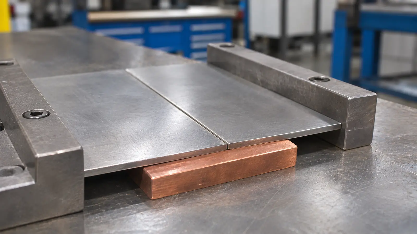
A suitable backing or chill bar may support the weld pool or help remove heat. A copper bar is sometimes used behind thin sheet, but its placement, contact, access and removal must match the material and approved joint. The wrong backing arrangement can introduce other defects or obstruct assembly.
Backing is not always practical inside a closed enclosure. Where access is limited, the design may need a different joint configuration, welding sequence or fixture plan. Do not treat copper backing as a requirement for every thin-metal weld.
Hold the part consistently without overclamping
Fixtures help hold thin panels at the specified gap and orientation while welding starts. Good support keeps an unsupported edge from moving away from the pool. Yet strong clamping can also restrict movement, leave stress, or change fit after release. The design should consider the part after cooling, not just while it is restrained.
This is where burn-through and distortion overlap in production but remain different topics. Burn-through is missing metal from local melting. Distortion is a change in the overall part shape. The separate welding distortion Cluster owns the detailed sequence-versus-restraint comparison; its proposed URL must be checked before linking.
How should a thin-sheet trial be verified?
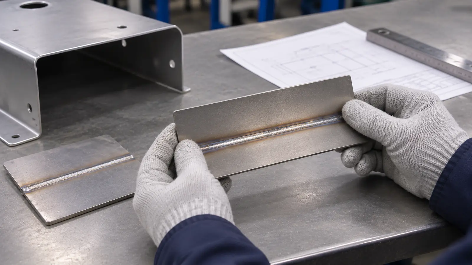
Use a first-off part or test joint made with the intended grade, thickness, gap, backing and fixture. Record the approved settings and method. Inspect the finished joint against the drawing after it cools and the fixture is released. A process change should not be called successful because no hole appeared in one photograph.
The trial should confirm the required joint size and continuity as well as fit and finish. Check the underside when access permits, but do not read a sound root condition from appearance alone if the application requires further testing.
How is a burn-through opening inspected and judged?
Visual examination usually makes a through-hole easy to locate. Record its size and where it meets the weld. Look for related melted-back edges and whether nearby joints show the same pattern. Dimensional checks can establish whether the sheet has also pulled out of tolerance.
Acceptance is a separate decision. The inspector needs the drawing, material, joint type, service conditions, applicable code and inspection plan. A small hole in a sealed enclosure may be critical because it can leak. A missing section in a loaded bracket can affect the intended connection. The same hole size is not automatically acceptable or rejectable in every use.
A close-up photo can establish a visible opening but not every hidden condition around it. If the component has important structural or sealing demands, a qualified reviewer should decide whether additional testing is needed. The Pillar guide covers inspection choices across several defect types; the present article stays with burn-through.
Can a burned-through panel be repaired?
Sometimes, but no single repair fits every joint. Adding filler over a hole without addressing thin edges, lost support or the approved weld size may leave a poor connection. Repair may also change panel flatness and affect coating or final assembly. A qualified engineer or welding supervisor must determine an authorized repair method.
Where repair is allowed, the affected material and joint need evaluation before controlled preparation and rewelding under the relevant procedure. The corrected area then requires the specified inspection. Some thin parts may be better replaced if repair would exceed the drawing or process limits.
Keep the original defect record and the correction record connected to the batch. Otherwise, the team may see a repaired surface without learning why the hole occurred. Meco’s fabrication and welding capabilities provide the service context for discussing these production choices.
What should a manufacturer send for an engineering review?
The useful starting point is a drawing that identifies the joint, not just a photo of the hole. Include sheet grade and thickness, joint design, expected quantity, weld position and any gap or backing restrictions. Add a marked photo showing the exact location and the inspection result if one exists.
If the issue started after a change, provide relevant fixture, forming, cutting or procedure revisions. Where applicable, include the required leak, dimensional or other acceptance criteria. These details help narrow the manufacturing choices before a quote or process revision.
For product planning, Meco’s R&D engineering support addresses design and manufacturing review. For an existing production issue, the same information supports a clear conversation about investigation, corrective action and verification.
Plan a Thin-Metal Weld That Can Be Built and Checked
Share the drawing, thickness, joint fit, target finish, quantity and inspection needs. Meco can review the manufacturing and quality requirements.
- Drawing, material grade and sheet thickness
- Joint arrangement and measured gaps
- Backing and fixture access restrictions
- Inspection criteria and production quantity
References and sources
- Miller Electric. Successfully Welding Sheet Metal with MIG and TIG.
- Miller Electric. Reducing Rework in Manufacturing: 5 Tips To Improve MIG Welding Sheet Metal.
- Miller Electric. Troubleshooting Weld Defects.
- TWI. Welding Imperfections and Materials, burn-through training definition (historical reference, not a current code).
