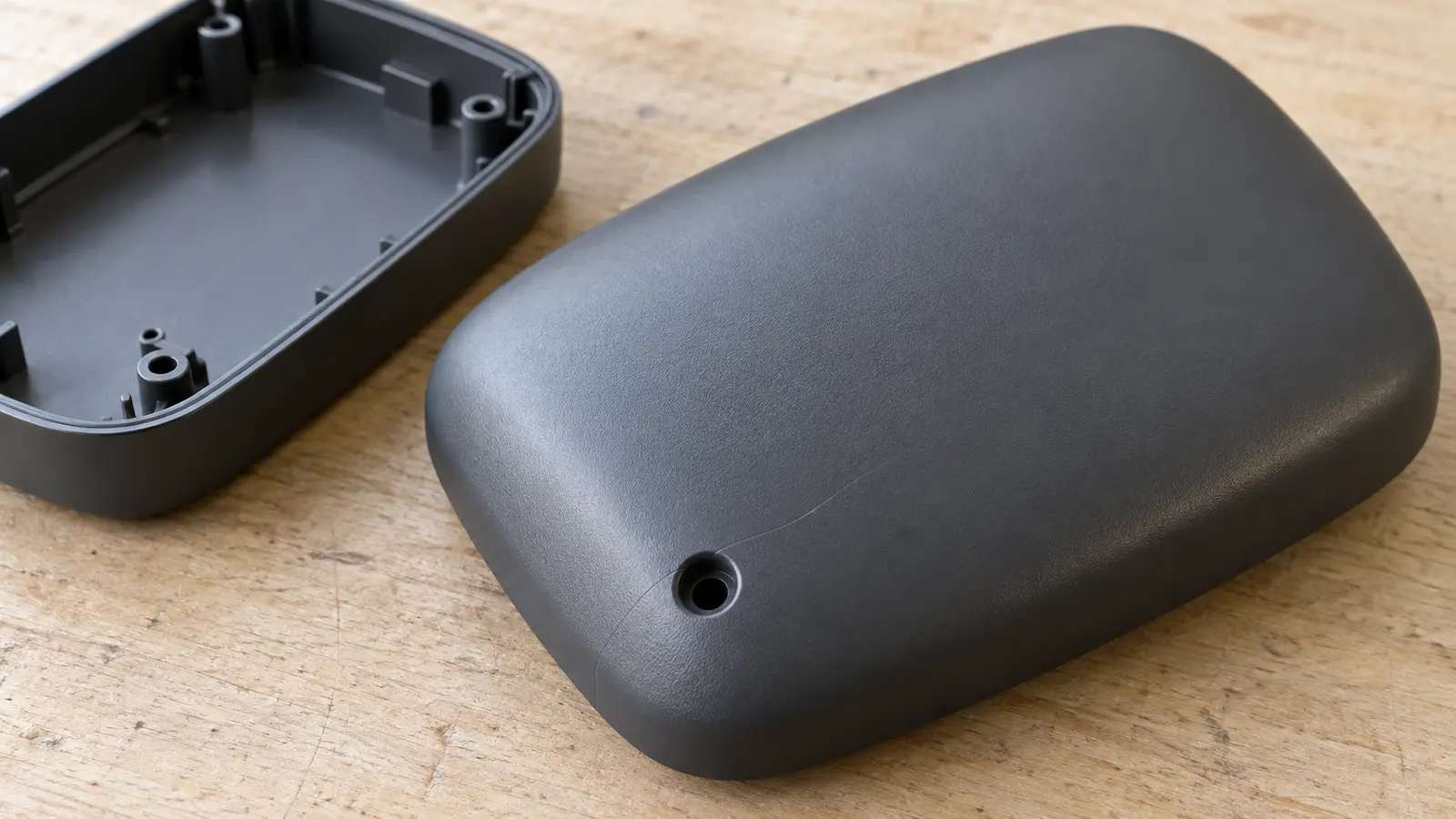
Knit lines form where separate flows of melted plastic meet inside a mold. A line near a hole, screw boss or flexible clip may need a strength check, even if the part looks complete.
Its appearance alone cannot show how well the flows bonded. Review the line's location, plastic grade and the loads the finished part must carry.
A molded cover can come out looking complete, with a thin line starting at one screw hole.
Whether that line matters depends on what the cover does. A mark on a hidden wall may have little effect, while one across a tab that bends every time the cover opens deserves a closer look.
Meco's injection molding defects overview covers the wider group of visible and functional problems. This article focuses on knit lines and the point where appearance alone stops being a useful guide.
Start with a marked part, its drawing and the exact plastic grade. Knowing where the line is and what loads the part sees gives the molding team a better starting point than changing machine settings right away.
What are knit lines in injection molding?
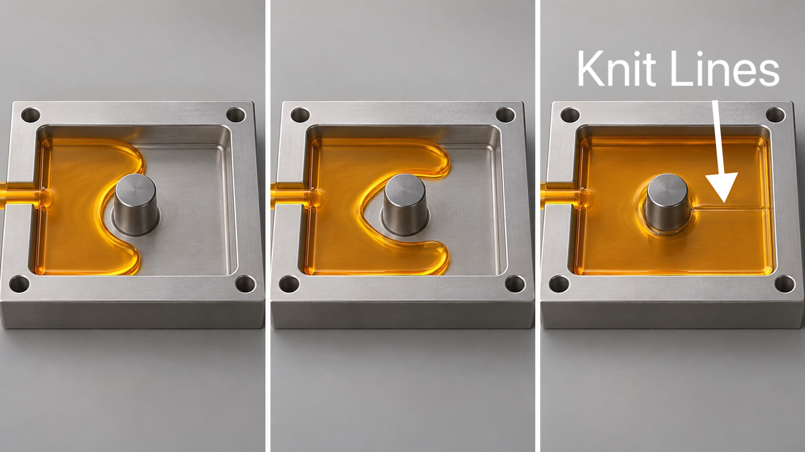
A knit line is the mark left where two or more flows of melted plastic meet inside a mold. It often appears behind a pin, hole or feature that splits the flow. A part can be fully filled and still have a knit line.
Imagine plastic moving around a metal pin inside the mold. It travels along both sides, then joins again behind the pin. That meeting area can leave a fine seam, a narrow change in gloss or a slight color change on the finished part.
Are knit lines and weld lines the same?
In everyday molding discussions, knit line and weld line often describe the same joining mark. Some technical guides also use “meld line” when the flows meet at a wider angle and move together rather than meeting nearly head-on.
The distinction can matter to strength, but the terms are not always used in the same way. Ask the molding engineer to describe the flow and joining conditions, not just the label. Autodesk explains both forms in its weld-line guidance.
Check that you are looking at the right line
A flow line is usually a surface wave or streak linked to how plastic moved or cooled. A parting line marks where mold sections close together. Neither one automatically means two plastic flows met there.
If you are new to the filling stage, Meco explains how plastic injection molding works. A handling scratch can look like a thin line too. Follow the mark toward a hole, gate or feature, then compare several molded parts.
Why do knit lines form when plastic flows meet?
Two flows can meet without forming the same bond as one continuous flow. Their temperature, speed, direction and the air around the meeting point all affect how well the material joins.
The empty shape inside the mold is called the cavity. Melted plastic enters through an opening called the gate, and its moving leading edge is the flow front. Plastic touching the cooler steel begins to form a skin while warmer material continues moving behind it.
A hole can split one flow into two
When plastic reaches a hole-forming pin, it cannot pass through the pin. The flow divides, moves around both sides, then may meet again on the far side. One gate is enough to create this joining line.
Parts fed from two gates can also have meeting points. Ribs, openings and inserts may redirect the flow too. The finished line can show where the flows met, but it cannot show how well they bonded.
Why the meeting temperature matters
The plastic's long molecules need enough movement at the meeting point to join across the boundary. If a flow front has cooled too much, the two sides may touch without forming the same bond as a region filled by one continuous flow.
Covestro notes that a small groove at the meeting surface can focus force into a narrow area. Its material tests show why strength, stretch before break and impact behavior should be considered separately. Those findings apply to the tested material and shape, not every molded part.
Air and added fibers can change the result
Air must escape as the cavity fills. A vent is a very small opening that lets air out without letting much melted plastic pass. Air trapped near a meeting point may interfere with bonding.
Some resins contain short glass fibers to make them stiffer. Fibers may line up with the flow instead of crossing the joining boundary. A glass-filled grade can therefore behave differently from an unfilled grade, even when their visible lines look similar.
When can knit lines affect part strength?
A knit line needs closer review when it crosses an area that bends, holds a screw, carries weight, seals a product or takes repeated force. A visible line on a low-stress surface may be acceptable if the part meets its agreed requirements.
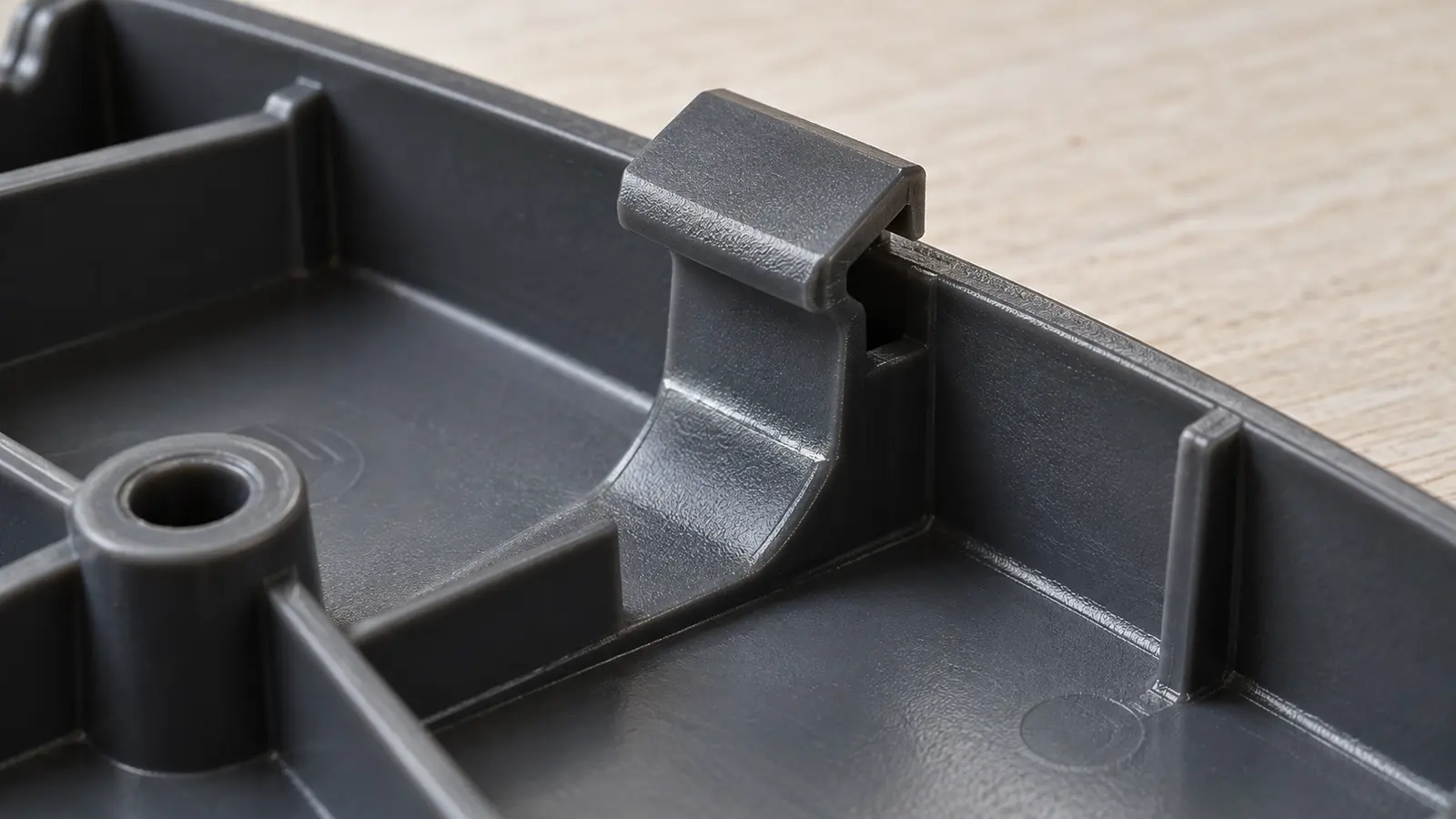
Picture a molded control cover with a snap-fit tab. The tab bends during assembly, then catches a matching edge. If a joining line crosses the tab's base, repeated bending may put force across that joined area.
What does the part have to withstand?
Before calling a line a defect, ask what happens to that exact area in use. The part may face a one-time assembly force, an impact, a screw-tightening load or a small load that stays on it for years.
Force pulling across a joining line is not the same as force running along it. Engineers should review the expected load direction instead of treating every line as equally risky.
| Line location | Possible concern | Useful next check |
|---|---|---|
| Hidden, lightly loaded wall | Appearance or local surface quality | Agreed visual limits and normal fit check |
| Base of a flexible clip | Crack during assembly or repeated use | Clip load, cycles and failure location |
| Near a screw hole | Crack under tightening or service load | Fastener load and mounted-part test |
| Thin load-bearing rib | Reduced margin at a stressed section | Relevant part-load test and geometry review |
| Sealing or fluid-contact edge | Leak path or loss of sealing force | Application-specific leak or pressure test |
Why a faint line is not proof of a strong joint
Surface gloss changes with lighting, texture and color. A joint that looks better may still have a weakness below the surface. The opposite can also happen: a visible line may meet the requirements for a part with little local stress.
Covestro's tests on a particular polycarbonate show that a joined sample can keep much of its initial yield strength yet stretch less before breaking. Use the exact resin grade and application to choose a test. A broad name such as ABS, PC or nylon does not identify every filler, color package or performance requirement.
What clues can help you find the cause?
Start with where the line sits, whether it repeats and what changed before it appeared. Those clues can point toward the flow path, a process change or a local mold condition.
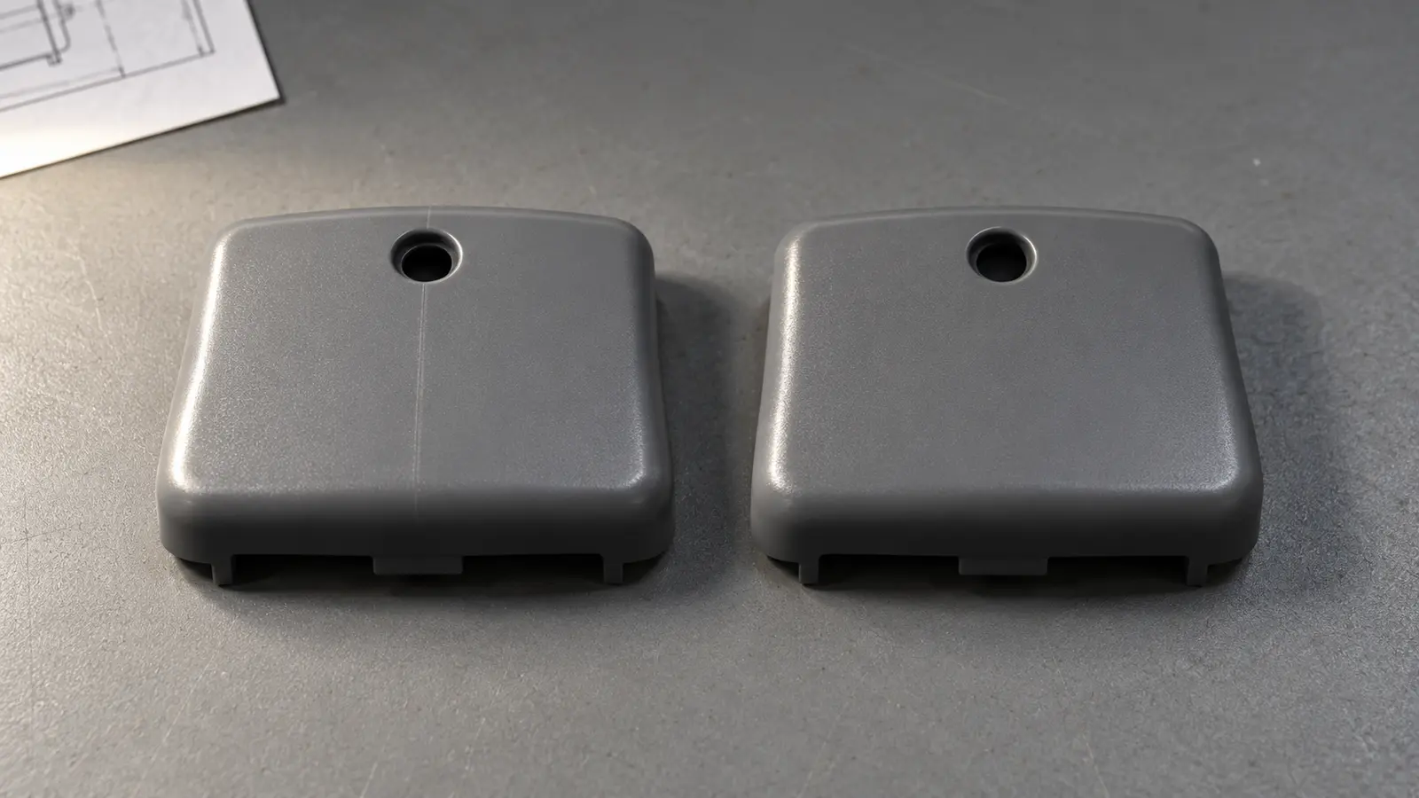
Lay out parts from several cycles. If the mold makes more than one part at a time, keep cavity numbers separate. A cavity is one shaped space that produces one part, and mixing cavities can hide a problem that affects only one of them.
Take one photo of the whole part and another close enough to show the line. Mark its location on the drawing. If an accepted sample exists, compare it under the same light and at the same angle.
| What you see | What to check first | Why it matters |
|---|---|---|
| Line starts behind a hole | Flow split, gate position and hole location | The two fronts may rejoin after passing the pin |
| Line appears between two gates | Fill balance and which front arrives first | Entry timing can move the meeting point |
| Line only on one cavity | That cavity's gate, temperature and vent | The issue may be local to one flow path |
| Line grew after a resin change | Exact grade, drying and process range | Grades can differ in flow and bonding behavior |
| Line changes after startup | Warm-up, actual temperatures and stability | Early cycles may differ from steady production |
| Crack follows the line | Service load, failure location and sample history | Appearance checks are no longer enough |
Do not confuse a line with missing plastic. When a rib or corner has not fully formed, the first issue is incomplete filling. Meco's short shot troubleshooting article explains that different problem.
If the line first appeared after mold maintenance, note the work completed. If it appeared after a material change, record the full resin grade, color and lot. A clear history makes controlled checks more useful.
Which molding conditions should you check first?
Compare the current run with the approved material guidance and the last good setup. Check actual temperatures, filling behavior and venting before changing several machine settings at once.
Check melt and mold temperature separately
Melt temperature describes the melted plastic. Mold temperature describes the steel surface that shapes and cools the part. Both affect how warm the flow fronts are when they meet.
A heater setting is not the same as a verified local temperature. Ask the process engineer to check measured values and stability. A warmer setup can help some materials, but excessive heat may damage resin or change size and cooling time.
Review injection speed and the filling stage
Injection speed controls how quickly plastic enters the cavity. A slow flow front has more time to cool before meeting another front. A different speed profile may help a difficult path fill while the fronts are still warm.
Speed changes do not always work in one direction. Too much speed through a small gate can create other defects or material damage. Compare the fill pattern and resin supplier's processing range, not only the machine display.
Do not overlook trapped air and packing
Air near the meeting point may need a way out. A toolmaker can check whether the nearby vent is open, blocked or poorly placed. Vent changes need care because an oversized opening can let plastic escape.
Packing pressure feeds extra plastic as the part starts to shrink after filling. It can help some conditions, but it cannot repair every weak meeting point created earlier. Raising pressure without a clear cause may also create injection molding flash.
Change one controlled factor at a time
Changing temperature, speed and packing in one trial makes it hard to know what helped. Change one controlled factor where practical, keep its samples and watch for new defects as well as a less visible line.
The goal is a stable process that makes a part meeting its defined needs. If the same line remains in a high-stress location, the team may need to review the tool and part design.
Knit line near a loaded feature? Send the drawing, resin grade and sample photos. An engineer can review the flow path and help choose the next checks.
Talk to an EngineerWhen should you review the gate or part design?
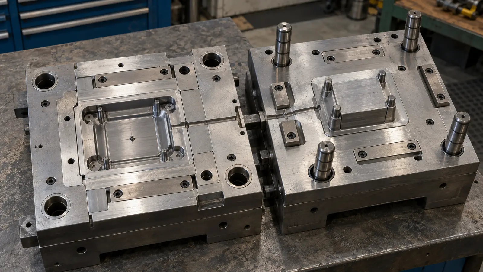
Review the gate and part shape when a knit line keeps forming at a critical feature or needs extreme settings to improve. Moving the meeting point can matter more than making the line look lighter.
The gate is the entrance through which plastic reaches the cavity. A runner is a channel that carries plastic toward that entrance. Their size, location and arrangement help decide which areas fill first and where separate fronts meet.
Move the meeting point away from heavy loads
If flow meets directly at the root of a snap-fit tab, moving the gate might shift that point toward a wider, less-stressed wall. It will not make every knit line disappear, but it may reduce risk at the feature that matters most.
A gate change can move the gate mark, change filling pressure, move another joining line or create a new appearance concern. Check the whole part after a change.
Check holes, wall changes and nearby features
A boss is a raised mounting feature, often around a screw hole. A rib is a thin wall used to support a part. Both can split or redirect plastic flow, especially when nearby walls are thin.
A design review may consider smoother wall transitions, a better route around openings or a different location for a critical feature. Those changes still need to preserve strength, assembly and fit. A thicker wall is not always right because it can bring other cooling problems.
Use simulation to compare options, then test real parts
Mold filling analysis is software that predicts how melted plastic moves through the tool. It can show likely meeting points before cutting steel, or help compare gate changes. Autodesk notes that weld-line predictions depend on the detail of the simulation model.
A predicted line is a design clue, not proof that the finished part will be weak or strong. Meco's R&D engineering support covers design and sampling stages where these decisions can be reviewed before production.
How do you know the improvement has worked?
Check the finished part against the original requirements, not only its surface appearance. A successful change should improve the joining area while keeping fit, size and function within requirements.
Use the same light, viewing angle and sample location as the agreed appearance check. Keep before-and-after parts from known cavities. This shows whether the line is less visible or has moved to another location.
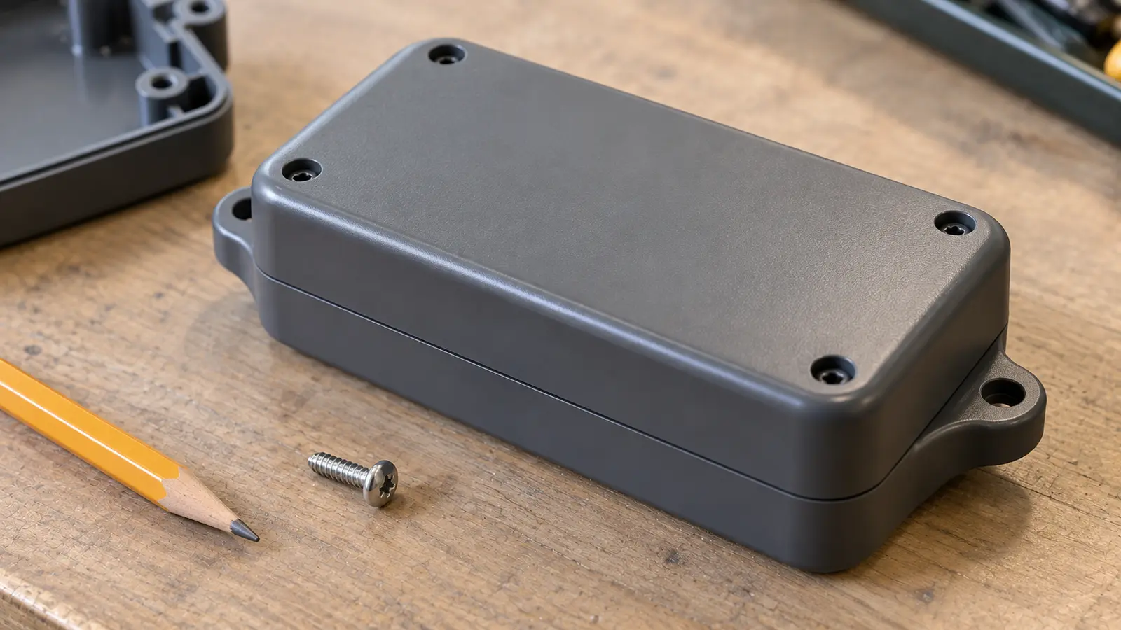
Next, check what the part must do. A cover may need to hold a screw, close repeatedly or keep water away from electronics. No single test covers all those needs.
Choose tests based on the real load
Engineers may use a tensile test, where a sample is pulled until a defined result or failure occurs. Comparing bars with and without knit lines can help study a material, but a small test bar cannot represent every finished part.
Covestro uses this type of comparison to show how a weld line can change how a sample stretches or breaks. It also notes that actual stress limits need finished-part validation.
Keep the rest of the part in view
A process change that improves the line might also change shrinkage, dimensions or release from the mold. Check drawing dimensions and look for flash, new surface marks or distortion. When molded parts join other components, mechanical assembly checks help confirm that the part fits and works.
This review also matters when moving from prototype to production. Repeat the approved check after startup, across the required cavities and over enough samples to judge stability. Keep the resin grade, approved settings, tool revision and test results together.
A line that becomes hard to see is an encouraging sign. It is an acceptable result only when the evidence meets the part's stated needs.
What should you agree on before tooling starts?
Identify critical load areas and agree on acceptance checks before the mold is made. The design team has more room to adjust the flow path before production tooling is complete.
This work is part of design for manufacturability (DFM), a review of whether a part can be made reliably. A drawing should show more than shape. It should also tell the manufacturer what the part must withstand.
Before tooling, agree on the expected load and direction at clips, screw holes, thin ribs and sealing edges. Define how visible a line may be, which cavities and samples to inspect, and what functional or strength test will be used.
When comparing suppliers, Meco's injection molding partner checklist covers tooling, production support and quality. For products that also need finishing or assembly, whole product manufacturing can bring those checks into one project plan.
Meco's custom injection molding services connect part review, tooling and molding. The practical aim is a part that meets its drawing and use requirements, not simply one without visible lines.
Discuss your molded part
Share the drawing, resin grade and line location with Meco. An engineer can review the part design, flow path and checks needed before the next production step.
- Design review. Gate, holes and loaded features.
- Process review. Material and molding conditions.
- Quality support. Samples, fit and required tests.
- Manufacturing experience. IATF 16949:2016 certified quality system.
References
- Covestro. Understanding and Optimizing Weld Lines in Thermoplastic Molding. Technical paper, April 2016. Material-specific examples; confirm current resin guidance before processing or approving a part.
- Autodesk. Troubleshooting weld lines and meld lines. Moldflow technical documentation.
- Autodesk. Utilizing and understanding weld line results in Moldflow. Updated 3 July 2026. Used for limits of predicted weld-line locations.
