By Meco Engineering Team
·
Published:
·
Updated:
·
14 min read
IATF 16949:2016
Short answer
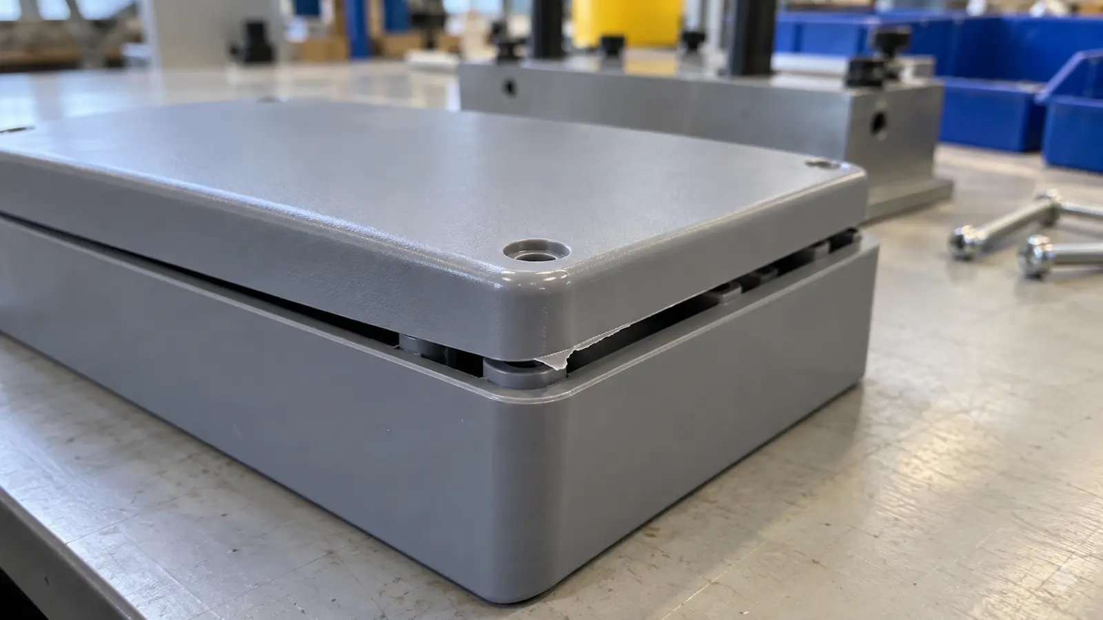
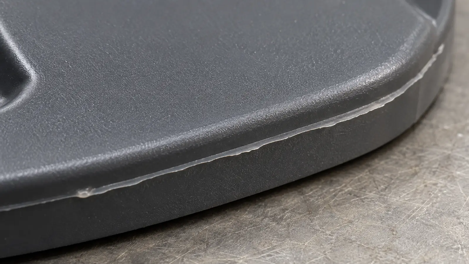
Injection molding flash is extra plastic left on a part after molding. It often looks like a thin lip along an edge or around a hole.
It forms when plastic escapes through a gap in the mold. The cause may be a worn mold, poor closing, or too much pressure.
A plastic cover may look fine until you try to fit it onto its base. A thin edge of extra plastic can stop it from closing. Even a small amount can cause a fit problem.
Flash can also block a hole, catch on a clip, or leave a sharp edge. Our injection molding defects guide explains other common problems that can affect a molded part.
Lowering pressure can reduce flash. But it can also leave part of the mold unfilled.
Before changing settings, compare a part with flash against a good part made in the same mold. Leave the extra plastic attached so you can see where it formed. Start there, then work through the checks below.
Key takeaways
- Recognize extra plastic. A visible mold seam is not always flash. Look for extra plastic beyond the shape the part should have.
- Follow the location. Flash in the same small spot calls for a check of that part of the mold.
- Check the whole part. After changing settings, check the whole part. A cleaner edge does not mean the part will fit or work.
- Set acceptance limits. Agree on where extra plastic is allowed and how much. A limit on part size does not answer that question.
- Change one setting at a time. Keep a sample so you can compare the results.
What does injection molding flash look like?
Compare the edge with the drawing or a good sample. A thin lip that sticks beyond the intended edge may be flash, while a faint line where the mold sections meet may be a normal seam. Check for extra material before treating a visible line as a defect.
That seam is called a parting line. It marks where the mold opens to release the part.
A small mark where plastic entered the mold is different too. That entry point is called the gate. A mark left there may need its own check, but it is not automatically flash.
Once you have found extra plastic, ask what it might stop the part from doing:
- Does it stop a cover from fitting onto its base?
- Does it sit under a rubber seal and leave a gap?
- Does it stop a clip from snapping into place?
- Could it break off or leave an edge that feels sharp?
What should you check where the flash appears?
Check whether the flash appears in the same place on each part. Then check when it started. These two details help you choose where to look next.
They are clues, so confirm the cause before changing settings or repairing the mold.
Some molds make several parts at once. Each space that forms one part is called a cavity. Keep track of which cavity made each sample.
Otherwise, you may miss a problem that affects only one of them.
| What you see | What to check first | Why it helps |
|---|---|---|
| Flash in the same small spot | The mold surfaces that meet at that spot | Wear, damage or dirt may leave a gap. |
| Flash around much of the edge | How the mold closes and the pressure used | The mold may open slightly under pressure. |
| Flash on only one part in a group | The cavity that made that part | One part of the mold may need attention. |
| Flash began after mold maintenance | How the mold was put back together | A fitted piece may not be in its correct position. |
| Flash began after a material change | The exact plastic grade and its required settings | Different plastics may flow into small gaps more easily. |
| Some parts have flash and others do not | Changes in temperature, plastic delivery or mold closing | The run may not be staying steady. |
Keep a few samples and take photos before removing the flash. Include a close view of the edge and a wider view that shows its location on the part. Note whether the problem began on the first trial, after maintenance, or during a run that had been making good parts.
Once you know the pattern, the next question is why plastic can get past the mold surfaces at all.
Why does plastic escape from a closed mold?
The machine pushes hot plastic into the mold under pressure. That pressure can push the mold sections apart. The machine also applies force to hold them closed.
Flash can form if the mold opens slightly or if its surfaces already have a gap.
The force holding the mold closed is called clamping force. The pressure of the plastic inside it is called cavity pressure. One holds the mold shut.
The other pushes against its inside surfaces.
Part size matters here. Pressure pushing against a wide surface creates more opening force than the same pressure pushing against a small one. A mold making several parts at once adds more area for that pressure to act on.
This is why a pressure setting alone cannot tell you whether the machine can hold the mold closed. The process engineer must check the part size, mold layout and machine together.
But more clamping force will not repair a worn edge or a badly fitted piece of the mold. Autodesk includes both mold fit and clamping in its flashing troubleshooting guidance. [1] The useful next step is to check the settings and the mold, rather than assume one must be the cause.
Which machine settings should you check first?
Start with the saved settings from the last good run. Compare them with the current settings and note anything that changed. Check the filling stage, the plastic and its temperature, then how the mold is held closed.
Each check answers a different question.
Check what happens before and after the mold fills
The machine first pushes melted plastic into the mold. It then keeps pressure on the plastic while it begins to cool and shrink. This second stage is called holding pressure.
It helps the part keep its required size and shape.
If the machine switches to holding too late, it may keep pushing quickly when the mold is already nearly full. Pressure can rise and create flash. Holding pressure that is too high can also push plastic into a gap.
A process engineer can run a controlled trial without the holding stage. This is called a fill-only trial. Comparing that sample with a normal sample helps show when flash starts.
If flash appears only after holding is added, check that stage closely. If it is already present during filling, also check how the mold closes and where plastic may be escaping. RJG explains this approach in its flash troubleshooting article. [2]
Check the plastic and its temperature
Resin is the plastic material used for molding. Check the exact resin grade, meaning the specific product named by its supplier. Two plastics with similar names may need different settings.
Our injection molding materials guide explains the main material choices.
Plastic that flows more easily may enter a small gap that it did not enter before. Too much heat can change how it flows or damage the material. BASF lists both as possible causes of flash. [3]
Check the melt temperature, which is the temperature of the melted plastic. Follow the supplier's processing and drying guidance. Avoid lowering every heater setting at once.
That can make filling harder and leave you unsure which change helped.
Check whether the mold closes properly
Confirm the clamping setting and how the mold actually closes. The number on the machine screen does not show whether every contact surface meets properly.
If flash keeps appearing in one spot, inspect that spot before adding more force. Work within the machine and mold limits. Have the process engineer or toolmaker handle these checks and any controlled trials.
Common mistake. Changing speed, pressure and temperature together makes it hard to know what helped. During an approved trial, change one setting at a time and keep a sample of the result.
Why can lowering pressure leave plastic missing?
Lower pressure may stop plastic escaping at one edge, but also stop it reaching another part of the mold. That incomplete part is called a short shot. The change helps only if it removes flash while still making a complete part that meets the drawing.
For example, imagine a cover with a thin clip on one side and flash on the other. You lower the pressure. The flash disappears, but the end of the clip no longer forms.
The cover now looks cleaner, yet the clip cannot hold it in place.
That result tells you to check both areas. The flashed edge may have a gap. The thin clip may be hard to fill.
Increasing pressure again could fill the clip and bring the flash back.
Engineers call the range of settings that makes good parts the process window. If every setting gives you either flash or missing plastic, review the mold and part shape together. There may be no suitable range with the current setup.
Meco's custom injection molding services bring part design, mold work and molding into the same review. The aim is a complete part that fits, rather than one edge that looks better.
When should you check the mold itself?
Check the mold closely when flash keeps returning in the same place, starts after maintenance, or disappears only at settings that cause other defects. These patterns suggest that changing pressure alone may not solve the problem. Tooling here means the mold and the parts fitted inside it.
Check the surfaces that should keep plastic in
Around a hole or opening, two mold surfaces may meet to keep plastic out of that space. This contact area is called a shutoff. If it wears or no longer meets properly, plastic can slip between the surfaces.
An insert is a separate piece fitted into the mold to form part of the shape. If it is put back in the wrong position after maintenance, it may leave a gap. Dirt or stuck plastic can also stop mold surfaces from meeting.
Small pins push the cooled part out of the mold. These are called ejector pins. If the space around a pin becomes too wide through wear, plastic may enter it and form flash around the pin mark.
Check air passages and mold support
Air needs a way out as plastic fills the mold. Small passages called vents let it escape. If a vent is too deep for the plastic being used, plastic may escape there too.
Have the toolmaker check its size against the material requirements. [1]
The mold can also bend slightly under pressure and open a gap. It may look fully closed when the machine is stopped. The toolmaker should check how the mold is supported as well as how its surfaces fit. [1, 2]
These issues can occur in a new mold as well as an old one. Our plastic injection molding services include the wider molding process. Mold inspection and repair need qualified staff and equipment made safe for maintenance.
Flash keeps coming back? Send photos with the flash still attached, the plastic grade and a note of recent changes. An engineer can help you choose the next check.
How do you know the fix has worked?
After changing the settings or repairing the mold, check several parts from every cavity. Look for flash, missing plastic and changes in size. Then test the fit or function that matters.
One clean-looking part is a useful sign, but you need repeated good results before approving the change for production.
- Check before trimming. Compare the extra plastic with the drawing or agreed sample.
- Check the whole shape. Look closely at thin sections, clips and corners that may be hard to fill.
- Check size and fit. Measure important dimensions and try the part with its matching component where required.
- Check repeated results. Include all cavities and the agreed checks after startup or a restart.
- Save the result. Record the settings, plastic grade, mold work and inspection results that were approved.
Part weight can help show that the amount of plastic has changed. It cannot tell you whether a clip is complete or a cover fits. Use it alongside measurements and fit checks.
Flash removal may be allowed as a separate finishing step. Agree on the method and check for damaged edges, loose pieces of plastic and changes in fit. Removing the extra plastic does not fix the reason it formed.
What can you decide before the mold is made?
Once the current run is stable, use what you learned to plan the next mold. Decide where flash would affect the part's use and how those areas will be checked. Review these requirements before the mold is made, so the team can plan where its sections meet and how they will keep plastic in.
This review is often called DFM, or design for manufacturability. It means checking whether the design can be made reliably. For flash, start with four questions:
- Where will mold joints meet a cover edge, seal or visible surface?
- How will the mold surfaces keep plastic out of holes and openings?
- Will thin or long sections need pressure that could make another area leak?
- How will the team check these areas before and after any agreed trimming?
Meco lists a standard molding tolerance of 0.05 mm, about 0.002 in, for its custom injection molding work. A tolerance is the allowed change from the stated part size. It does not say how much flash is allowed.
Set that limit separately for the areas that matter.
For parts that join other components, review them together. Our mechanical assembly guide explains the wider fit checks. Meco makes parts and assembles them, so we can consider how a plastic edge will affect the finished product.
Discuss your molded part
Send the drawing, plastic grade and photos taken before trimming. An engineer will review them and help you choose the next step.
- Design feedback. Part shape and mold needs.
- Quality support. What to measure and check.
- Assembly review. How the part fits with other components.
About the author
Meco Engineering Team
The Meco Engineering Team draws on over 30 years of manufacturing experience across injection molding, machining, casting, surface finishing and assembly.
Our engineers help customers make parts that meet their size, cost and delivery needs. For molded parts, we also check how edges and dimensions affect the next assembly step.
- Specialisms. Part and mold review, plastic selection and assembly.
- Equipment. A coordinate measuring machine (CMM) measures part size and shape.
- Quality systems. First article inspection (FAI) checks the first parts against the drawing. The production part approval process (PPAP) records evidence for approval. Material records help trace which plastic was used.
- Reviewed by. Meco engineering and quality review is pending.
Meet the engineering team or talk to an engineer directly.
IATF 16949:2016 certified. 30+ years in turnkey manufacturing. 40+ in-house processes. Global production with North American support.
References and sources
- Autodesk. Troubleshooting flashing problems Moldflow documentation.
- RJG. The Two Causes of Flash and How to Troubleshoot Them
- BASF. Injection-Molding Problems in Engineering Thermoplastics Flash, pp. 28 to 29.
