
The right CNC machining tolerance is the loosest one that still lets your part work. For most metal parts, a general tolerance of about ±0.1 mm to ±0.005 mm (roughly ±0.004 in to ±0.0002 in) covers the job, and you only tighten specific features that actually need it. Picking a tolerance that is tighter than the part needs is the fastest way to blow up your cost and your lead time for no real gain.
That sounds simple, but the hard part is knowing which features need tight control and which ones don't. This guide walks you through it in plain English: what tolerance really means, how the ISO 2768 tolerance classes work, what each CNC process can actually hold, and how to read a machining tolerance chart without over-spending.

What Does CNC Machining Tolerance Actually Mean?
A tolerance is the amount a finished size is allowed to differ from the number on your drawing. No machine cuts perfectly. Even two parts run back to back on the same machine come out slightly different.
So instead of asking for one exact number, you give a range. If a hole is drawn at 10 mm with a tolerance of ±0.05 mm, any hole between 9.95 mm and 10.05 mm passes.
This range is also called CNC dimensional accuracy. The tighter the range, the harder the machine has to work to stay inside it, and the more it costs you.
Here's the thing most new buyers miss: you don't have to tolerance every dimension the same way. You tighten the features that mate with other parts, seal, or rotate, and you let everything else ride on a general tolerance. That single habit saves more money than any other tolerancing decision.
What Is ISO 2768 and What Do f, m, c, and v Mean?
ISO 2768 is the international standard for "general" tolerances. It's the safety net for every dimension on your drawing that you didn't give a specific tolerance to. Instead of writing ±0.1 mm next to fifty different sizes, you write one note like "General tolerances per ISO 2768-m," and the standard fills in the rest based on how big each feature is.
The standard, published by the International Organization for Standardization (ISO 2768-1), splits general tolerances into four classes. They go from tightest to loosest: fine (f), medium (m), coarse (c), and very coarse (v). Most machined metal parts use medium (m). Fine (f) is for parts that need a bit more control without going to a full custom tolerance.
| Nominal size range (mm) | f (fine) | m (medium) | c (coarse) | v (very coarse) |
|---|---|---|---|---|
| 0.5 up to 3 | ±0.05 | ±0.1 | ±0.2 | — |
| over 3 up to 6 | ±0.05 | ±0.1 | ±0.3 | ±0.5 |
| over 6 up to 30 | ±0.1 | ±0.2 | ±0.5 | ±1.0 |
| over 30 up to 120 | ±0.15 | ±0.3 | ±0.8 | ±1.5 |
| over 120 up to 400 | ±0.2 | ±0.5 | ±1.2 | ±2.5 |
| over 400 up to 1000 | ±0.3 | ±0.8 | ±2.0 | ±4.0 |
Notice how the allowed range grows as the part gets bigger. A 5 mm feature at class "m" is held to ±0.1 mm, but a 300 mm feature at the same class gets ±0.5 mm. That's on purpose. Bigger parts move more with heat and clamping, so the standard gives them more room. There's a second part of the standard, ISO 2768-2, that covers shape and position (things like flatness and squareness) using classes H, K, and L.
Quick takeaway
If you only remember one thing about CNC tolerance standards: put a single ISO 2768 note on your drawing (medium "m" is the safe default), then add tight tolerances only on the handful of features that truly need them. That keeps your part affordable and still precise where it counts.
What Tolerance Can Each CNC Process Hold?
Different operations have different natural accuracy. A turning lathe holding a round shaft can usually run tighter than a long end mill reaching deep into a pocket. Knowing the realistic limits helps you avoid asking for something a process can't comfortably deliver.
The numbers below are typical, achievable ranges for well-controlled shops on common metals. They aren't the absolute floor, and they aren't promises for every material or feature. Use them as a sanity check on your drawing.
| CNC operation | Typical achievable tolerance | Best for |
|---|---|---|
| CNC turning (lathe) | ±0.025 mm (±0.001 in) | Round shafts, pins, fittings |
| CNC milling (3-axis) | ±0.025 to ±0.05 mm | Brackets, plates, housings |
| CNC drilling | ±0.05 to ±0.1 mm | Clearance and bolt holes |
| Reaming / boring | ±0.01 mm | Precise bores and bearing seats |
| 5-axis milling | ±0.01 mm or tighter | Complex curved or angled parts |
| Grinding / lapping | ±0.005 mm or better | Gauge surfaces, ultra-precision |
When Do You Actually Need ±0.01mm Machining?
Tolerances around ±0.01mm machining belong to a small group of parts: bearing fits, sealing faces, sensor mounts, and mating surfaces where a few microns change how the assembly works. In our experience, fewer than one in five features on a typical drawing genuinely need this level of control.
For the parts that do, the work usually moves to a more capable setup. Our 5-axis CNC machining service holds tolerances down to 0.005 mm on key features, which is where aerospace, medical, and high-end automotive parts tend to live. If your whole part doesn't need that, we machine the critical features tight and the rest to a general class. That's precision CNC tolerance applied where it earns its cost.
Why Do Tighter Tolerances Cost More?
Cost doesn't climb in a straight line as you tighten a tolerance. It climbs like a ski jump. Loosening a tolerance is cheap. Tightening it past what a process naturally holds gets expensive fast.
According to an analysis by Modus Advanced, moving from a rough tolerance to a precision tolerance can raise part cost about 4x, and ultra-precision work can cost up to 24x more than standard. The reasons stack up: slower cutting, special fixtures, more scrap, extra inspection, and sometimes a temperature-controlled room.
There's also a physics problem people forget. Metal grows and shrinks with heat. A 300 mm aluminum part changes size by roughly 0.07 mm for every 10°C swing in temperature. If you spec a tolerance tighter than that natural movement, you're fighting the laws of nature, not the machinist.
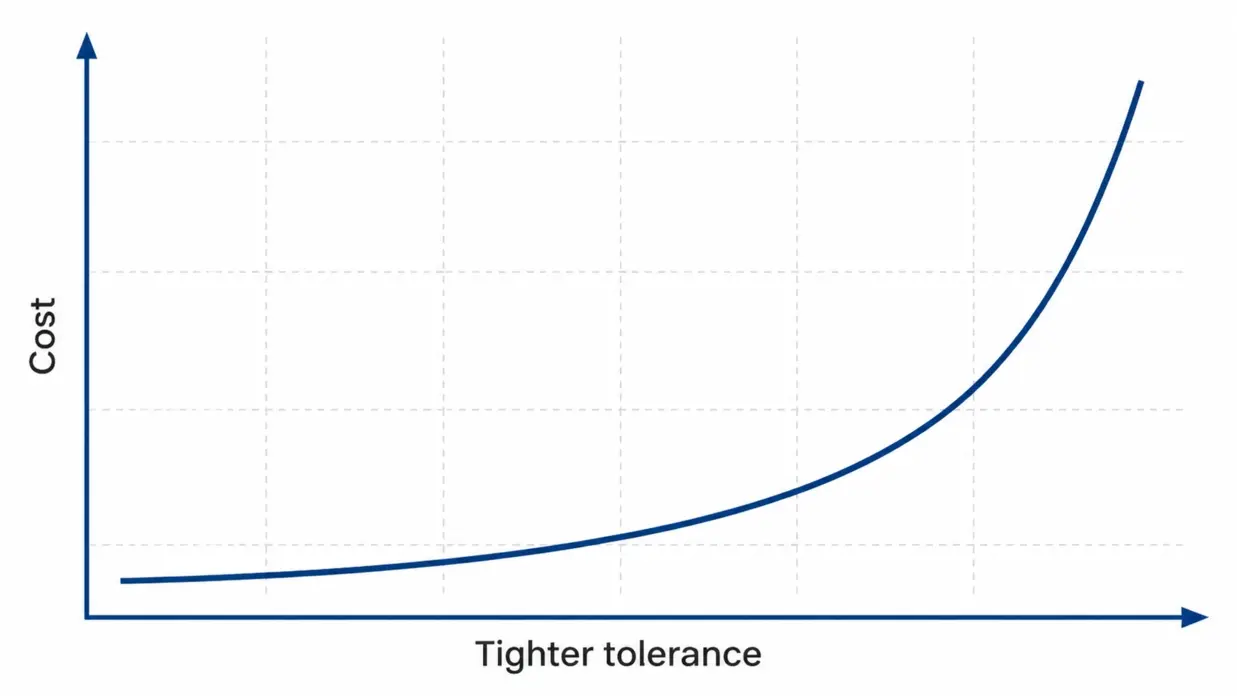
The cost impact of tight tolerances
Going from ±0.13 mm (±0.005 in) to ±0.025 mm (±0.001 in) on a feature often doubles its cost. Pushing to ±0.0025 mm (±0.0001 in) can cost up to 24 times the standard rate. Before you tighten a number, ask one question: does the part fail if this dimension drifts? If not, leave it on the general tolerance.
How Does Surface Roughness (Ra) Fit In?
Tolerance controls size. Surface roughness Ra controls texture, meaning how smooth or rough the finished surface feels. They're two separate specs, and mixing them up is a common and costly mistake.
Ra is the average height of the tiny peaks and valleys left by the cutting tool, measured in micrometers (µm). A lower number means a smoother surface. A standard milled face lands around Ra 3.2 µm. A sealing surface might need Ra 0.8 µm. A polished gauge surface goes far smoother.
| Ra (µm) | Ra (µin) | Typical process | Where it's used |
|---|---|---|---|
| 6.3 | 250 | Rough milling, turning | Non-contact, clearance faces |
| 3.2 | 125 | Standard milling / turning | Brackets, general surfaces |
| 1.6 | 63 | Fine milling, wire EDM | O-ring grooves, press fits |
| 0.8 | 32 | Fine turning, grinding | High-pressure seals |
| 0.4 | 16 | Grinding, honing | Bearings, sliding surfaces |
| 0.1 | 4 | Lapping, superfinishing | Gauges, optical seats |
Just like tolerance, a smoother finish costs more. RapidDirect notes that over-specifying roughness can inflate part cost by more than 30%. So treat Ra the same way you treat tolerance: call out the tight value only where the surface seals, slides, or carries a coating. For a deeper reference, see our surface finish chart, and if you need finishing done, our surface finishing services cover anodizing, plating, and polishing.
When Should You Use GD&T Instead of Plus/Minus Tolerances?
Plain plus/minus tolerances work great for simple sizes: a length, a diameter, a hole position. But they fall short when the relationship between features matters more than any single size. That's where GD&T comes in.
GD&T stands for geometric dimensioning and tolerancing. It's a drawing language, set by the ASME Y14.5 standard, that controls things plus/minus can't, like how flat a surface is, how square two faces are, or how well a hole pattern lines up. Instead of saying "this hole is here, give or take," GD&T says "this hole must sit within a 0.1 mm zone relative to these reference surfaces."
The payoff is real. Used well, GD&T often lets you loosen individual sizes while still guaranteeing the parts assemble. That fights a problem called tolerance stack-up, where lots of small tolerances pile up across an assembly and push the final fit out of range.
When to spec GD&T
Reach for GD&T when parts must mate precisely, when hole patterns bolt to another part, when a surface must seal or run true, or when a simple plus/minus can't capture what "good" really means. For one length on a bracket, plus/minus is fine. For a rotating assembly or a sealed housing, GD&T usually pays for itself.
Getting datums and callouts right is part of good design for manufacturing. Our team works through this during early reviews; you can read more on our R&D and engineering page. Inspection of these features ties back to standards from bodies like NIST manufacturing metrology and dimensional methods from ASTM.
The 5 Most Common Over-Tolerancing Mistakes
After 30+ years of quoting parts, we see the same avoidable mistakes again and again. Each one adds cost without making the part work better. Here's our short checklist to run before you release a drawing.
- Tightening every dimension equally. Most features can ride on a general ISO 2768 class. Tighten only what mates, seals, or rotates.
- Spec'ing a smooth Ra everywhere. A mirror finish on a hidden surface is pure waste. Match Ra to function.
- Ignoring heat and material movement. Asking for a tolerance tighter than the part's natural thermal growth is a setup for scrap.
- Defaulting to CAD software tolerances. Many drawings inherit tiny default tolerances nobody chose. Always set them on purpose.
- Skipping a DFM review. A quick design-for-manufacturing check often loosens tolerances safely and cuts cost 15 to 30 percent.
How to Choose the Right Tolerance: A Simple Decision Framework
When a customer asks us how tight to go, we walk them through four quick questions. We call it the FACT check, and it works for almost any feature on a drawing.
F - Function
Does this dimension control how the part works? If it mates, seals, rotates, or carries a load, it may need a tight tolerance. If it's a cosmetic edge or open clearance, it doesn't.
A - Assembly
Does it fit against another part? If yes, think about the whole stack of parts, not just this one. This is where GD&T and tolerance stack-up math matter.
C - Cost
What does the tighter number actually buy you? If halving the tolerance doubles the price and changes nothing about performance, leave it loose.
T - Test
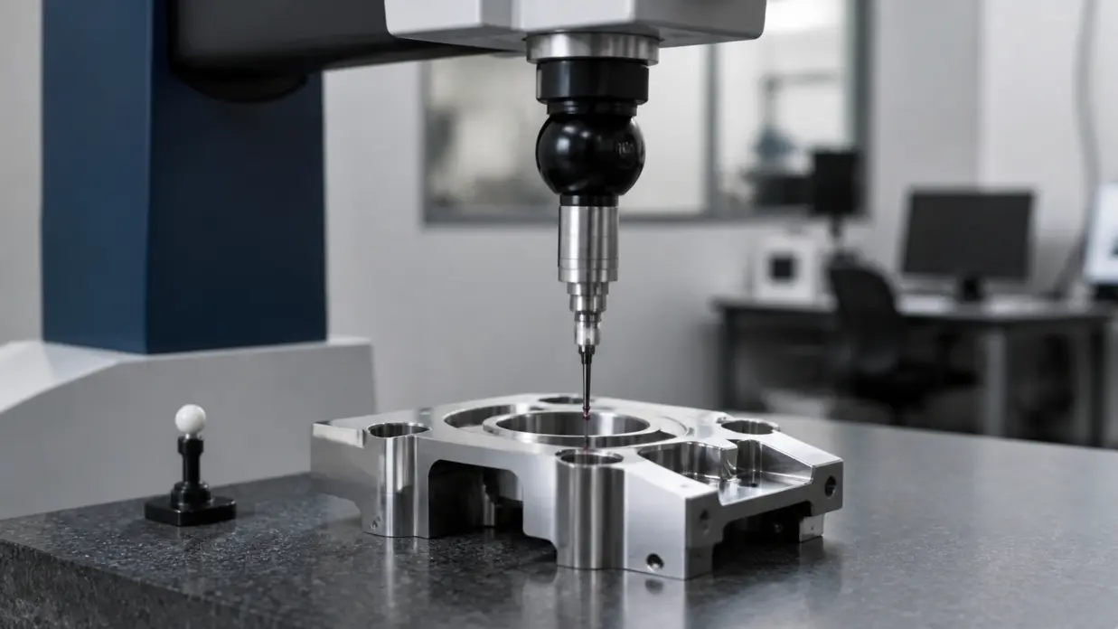
Can the tolerance be measured and proven? A tolerance you can't inspect is a tolerance you can't trust. We verify critical features on a CMM accurate to ±0.002 mm, with full first-article and PPAP documentation.
Run every critical feature through FACT, lean on ISO 2768 for the rest, and you'll land on a drawing that's precise where it matters and affordable everywhere else. If you'd rather have a second set of eyes, that's exactly what our DFM reviews are for. We'll flag the tolerances worth keeping and the ones quietly draining your budget.
Frequently Asked Questions
What is the standard CNC machining tolerance?
The standard general tolerance for CNC machined metal parts is about ±0.127 mm (±0.005 in), which lines up with ISO 2768 medium class for many sizes. Shops can hold tighter on specific features, but this is the typical baseline you get without calling out a special tolerance.
What does ±0.01mm tolerance mean?
It means the finished size can be up to 0.01 mm larger or smaller than the number on the drawing. For a 10 mm feature, anything from 9.99 mm to 10.01 mm passes. This is a precision-level tolerance used for bearing fits, seals, and other critical mating surfaces.
How tight a tolerance can a CNC machine hold?
Standard CNC machining holds around ±0.025 mm to ±0.05 mm comfortably. With the right setup, milling and turning can reach ±0.01 mm, and grinding or lapping can hit ±0.005 mm or better. Meco holds tolerances down to 0.005 mm on key features for demanding parts.
What do f, m, c, and v mean in ISO 2768?
They are the four general tolerance classes in ISO 2768-1: fine (f), medium (m), coarse (c), and very coarse (v). Fine is the tightest and very coarse is the loosest. Medium is the most common default for machined metal parts.
Why do tighter tolerances cost more?
Tighter tolerances need slower machining, special fixtures, more inspection, and they produce more scrap. Cost rises exponentially, not in a straight line. Moving from a standard to a precision tolerance can roughly double cost, and ultra-precision work can cost up to 24 times more than standard.
What is the difference between tolerance and surface roughness (Ra)?
Tolerance controls the size of a feature, while surface roughness Ra controls the texture or smoothness of a surface. A part can be the perfect size but too rough for a seal, or smooth but out of size. They are separate specs and should be chosen separately based on function.
When should I use GD&T instead of plus/minus tolerances?
Use GD&T when the relationship between features matters, such as flatness, squareness, or hole patterns that must align with another part. Plus/minus tolerances work well for simple sizes. GD&T often lets you loosen individual sizes while still guaranteeing parts assemble correctly.
Does material affect achievable tolerance?
Yes. Soft materials can flex away from the cutting tool, abrasive materials wear tools faster, and plastics expand with heat, all of which affect the tolerance a process can hold. Aluminum and steel hold tight tolerances well, while soft or heat-sensitive materials usually need a bit more room.
Get a Tolerance Review With Your Quote
Not sure which tolerances are worth the cost? Send us your drawing and our engineers will tell you exactly where to tighten and where to save, before you spend a dollar on tooling.
- Free DFM feedback that typically cuts cost 15 to 30 percent.
- Quote in under 24 hours with engineering review included as standard.
- Tight where it counts: tolerances held to 0.005 mm on critical features, verified on a CMM accurate to ±0.002 mm.
- IATF 16949:2016 certified with full FAI and PPAP documentation.
- Prototype to production: 10 pieces to 10 million+, no minimum order quantity.
