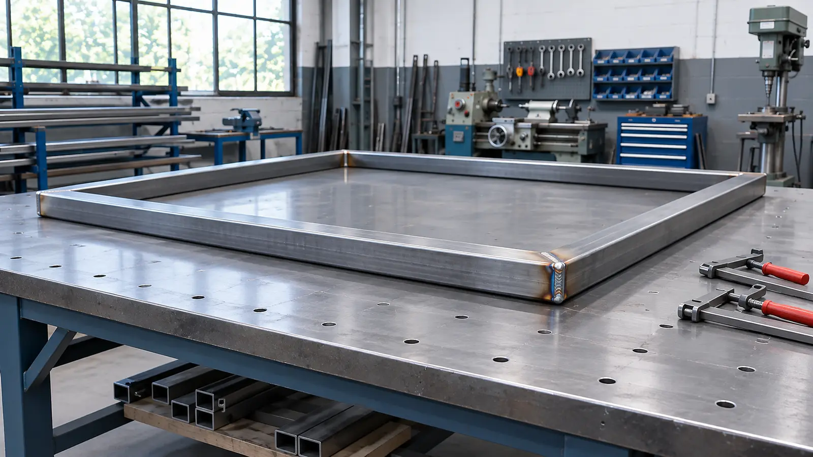
Welding distortion matters when heat changes a part’s shape enough to affect fit, alignment or the drawing limits. A sensible first response is to check where the movement starts, which welds pull the part out of shape and how the assembly is held during welding. Do not assume that more clamps or lower heat alone will solve it.
The best control is usually planned before welding: use the required weld size, suitable joint fit-up, a balanced sequence and fixtures that hold important features. Then check the part after it has cooled and been released from the fixture.
A steel machine frame may sit flat when its pieces are clamped together. After the seams are welded and the clamps come off, one corner can rise from the table. The welds may look smooth, but the mounting holes no longer line up with the next assembly.
The problem is not always an obviously bent panel. A long support may bow a little, or an enclosure side may tilt by a small angle. Those changes can still matter where a gasket, guide rail or mating bracket needs a controlled position.
This article explains how welding changes shape, why certain joints move more than others and how a team can limit that movement without weakening the weld. For a wider classification of weld imperfections, see Meco’s welding defects overview.
Key takeaways
- Welding distortion is a change in size or shape caused mainly by uneven heating and cooling, not proof that the weld bead is internally defective.
- Longitudinal and transverse shrinkage, angular movement, bowing, buckling and twisting affect different parts in different ways.
- Heat input, weld size, material, joint position, sequence and restraints interact. No single setting prevents all distortion.
- Fixtures can hold dimensions during welding, but excessive restraint can increase residual stress and raise cracking concerns in susceptible joints.
- Acceptance should be based on the cooled, released part and the drawing, not only how the assembly looks inside the jig.
What is welding distortion, and why does a weld pull metal out of shape?
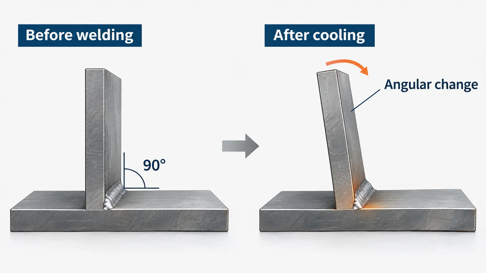
Welding distortion is a change in the size or shape of a metal part caused by welding. The metal next to the weld gets hot and expands. The cooler metal around it does not expand as much, so it resists that movement.
As the hot weld metal and nearby zone cool, they contract. The contraction is not spread evenly across the part. If the resulting forces are high enough to leave lasting movement, the part may be shorter, bent or twisted even after it reaches room temperature.
The heat-affected zone, or HAZ, is the base metal near the weld that becomes hot enough to change its properties without melting. The weld metal and HAZ both play a role in contraction. TWI explains how this uneven heating and cooling creates stress and permanent shape change.
A useful picture is a steel strip with one edge heated more than the other. When that edge cools and pulls, the strip can curve. A welded assembly is more complex because its joints, supports and other seams all resist or add to that pull.
That mechanism explains why distortion can occur even when the weld has acceptable fusion, profile and appearance. It is a dimensional problem that needs its own review. The next question is how the movement appears on a real part.
What shapes can welding distortion take?
Different movement patterns point to different weld locations and restraints. A team should describe what moved instead of using “warped” for every shape change.
| FORM | WHAT THE PART DOES | WHERE IT MAY MATTER |
|---|---|---|
| Transverse shrinkage | Pulls together across the weld | Joint gap or overall width |
| Longitudinal shrinkage | Shortens along the weld direction | Length of a rail or support |
| Angular distortion | One side rotates relative to the other | Bracket angle or panel squareness |
| Bowing or dishing | Curves along a length or across a broad sheet | Flat mounting surface or enclosure skin |
| Buckling | Thin area ripples or snaps into another shape | Wide, lightly supported sheet |
| Twisting | Corners rotate out of the same plane | Box frame or welded base |
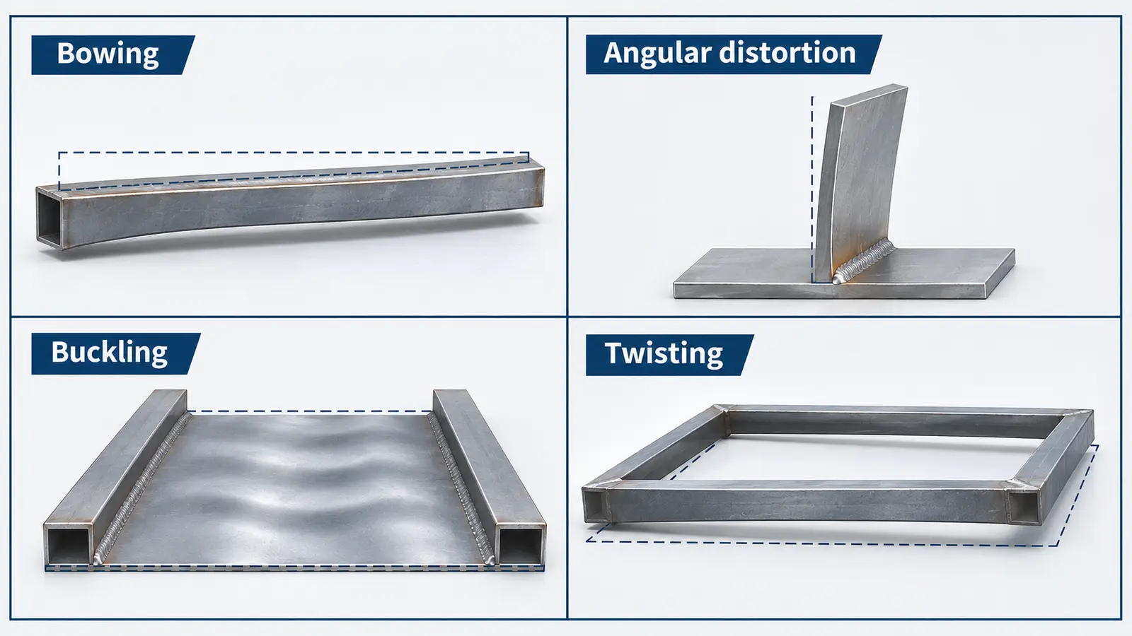
For example, welding one side of a long L-shaped support may draw that side inward and make the support bow. On a thin machine cover, several welds around a stiffener can leave ripples between the attachments. A box frame may twist when opposite corners do not experience similar shrinkage.
These forms may appear together. A part can get slightly shorter and also tilt. Measuring the change in more than one direction helps determine whether the main issue is local or spread through the assembly.
When does distortion become a quality concern?
Not every small change means a rejected part. The concern is whether the finished assembly meets the dimensions and use conditions set for the job. A visible curve on a hidden cover may be acceptable, while a small change on a precision mounting face may not be.
Imagine a fabricated base holding a linear guide. If welding pulls the rail mounts out of line, a slider may bind after assembly. On a hinged enclosure, a shifted edge can change the door gap or seal contact. A cosmetic panel has different priorities from a load-bearing bracket, but both can have controlled limits.
The drawing may specify flatness, straightness, hole position, perpendicularity or overall size. Flatness describes how closely a surface follows a plane. Perpendicularity describes whether two features stay at the intended right angle. The acceptance decision belongs to these requirements, not to a universal millimeter limit for welding distortion.
For assemblies built from several joined sheets, Meco’s sheet metal assembly guide provides wider context on fit and tolerance planning.
What makes some welded parts distort more than others?
The same welding method can leave different shape changes on two parts. The important question is how heat and shrinkage act on each part’s geometry.
Weld size, placement and joint gap
A larger weld deposit generally means more molten material that must contract. Making a bead larger than the approved design requires can add shrinkage without adding useful value. A wide joint gap can also require more filler metal and more passes.
Weld position matters as well. A weld far from the section’s middle can pull like a lever and bend the assembly. A balanced arrangement may reduce that turning effect, although the design must still meet its strength and access requirements.
Material and thickness
Thin sheet can be easy to buckle because it has less stiffness. Thicker plate may resist movement more strongly but still build significant residual stress. Residual stress means stress that remains inside the metal after the welding and cooling are finished.
Metals do not expand and conduct heat in the same way. Stainless steel and aluminum may need different distortion controls from carbon steel. This does not justify a universal ranking for every part, since alloy, thickness, joint geometry and process all matter.
Heat delivered and the number of passes
Heat input is the energy delivered along a weld. Travel speed, current, voltage and process efficiency affect it. A poorly chosen condition can heat too much surrounding material or fail to provide the fusion required by the procedure.
More passes create repeated heating and cooling. But cutting heat or the number of runs without checking fusion and bead size can create another problem. The approved welding procedure, not a generic “lowest heat” rule, sets the safe working range.
Fixtures, tack welds and assembly order
A tack weld is a short temporary or permanent weld used to hold parts in position for later joining. A jig or fixture locates and supports the assembly. Both can make the starting shape more repeatable.
Yet holding one side fixed can make the other side move, while very rigid restraint can trap stress. Also, joints welded early may pull later joints out of alignment. This is why distortion control must consider the whole assembly instead of one isolated seam.
How can a team trace the main source of movement?
Start by noting where the part changes shape: during tacking, after an early seam, after the final pass or only after it leaves the fixture. Photographs alone rarely show the full amount of distortion. Simple measurements taken at consistent stages are more useful.
Record material and thickness, drawing revision, joint gap, fixture setup, tack locations, weld size, pass sequence and approved parameters. Compare the first accepted build with the affected run before changing several controls at once.
| OBSERVED CLUE | CHECK FIRST | DOES NOT PROVE |
|---|---|---|
| A bracket tilts after one long fillet weld | Weld placement, size and sequence | That all settings must be lowered |
| A panel looks flat in the jig but bows when released | Fixture restraint and residual stress | That the fixture is defective |
| Thin sheet ripples between stiffeners | Heat distribution, stiffener layout and weld lengths | That one extra clamp will always help |
| A frame twists near the last welded corner | Order of welds, diagonals and tack layout | That the base material was bad |
| Movement rises after changing the joint gap | Fit-up, filler volume and pass count | That the welding process is unsuitable |
Consider a hypothetical run of welded conveyor supports. One corner begins to lift after the final long seam, although the jig holds the part square during the pass. The team checks whether a more balanced sequence can limit the final pull and whether measurements change after fixture release.
A controlled trial should change one planned factor at a time while keeping the qualified weld procedure and inspection needs intact. That produces evidence rather than a collection of guesses.
Which controls should be considered first: heat, sequence or fixturing?
These three choices solve different parts of the problem. Heat and weld volume affect how much contraction is introduced. Sequence changes how those pulls add together. Fixturing governs how the assembly is located and how much it can move during fabrication.
| CONTROL | BEST STARTING QUESTION | LIMIT OR TRADE-OFF |
|---|---|---|
| Heat and weld volume | Can the specified weld be made with less unnecessary deposited metal or heating? | Must keep fusion, size and the approved procedure |
| Weld sequence | Can the pulls be balanced across sides or spaced along the part? | Access, position and previous welds restrict the order |
| Fixturing and tacks | Are critical features positioned consistently during welding? | Release may reveal movement; high restraint adds stress |
If the weld is simply oversized, first check the approved weld size and fit-up. If movement follows the last seam on one side, sequence may offer more leverage. If every part begins with a different gap or position, better location and tacking may be the practical first fix.
The strongest plan often combines all three. It is not a contest to find the one “best” control, and it should never be a reason to depart from a qualified procedure.
Need welded parts to fit? Send the drawing, critical dimensions and planned weld locations so Meco can discuss a practical fabrication and fixture review.
Discuss Your ProjectHow can welding sequence reduce distortion?
A weld sequence is the planned order and direction of welds. The idea is to avoid putting all the contraction on one side before the opposite side has been joined.
On a frame with suitable access, alternate between opposite sides or move between separated joints. For a long seam, approved skip welding uses shorter weld lengths placed at separated positions. Back-step welding uses short sections deposited opposite to the overall direction of progress. These techniques can spread the heating more evenly, but their suitability depends on the joint and procedure.
Balanced welding can also help a double-sided joint. Welding comparable regions on opposing sides may reduce angular change. It is not an instruction to add an extra weld that the drawing does not require.
Meco’s custom fabrication and welding capability page explains the wider production path from cutting and forming to joined assemblies. Distortion prevention works best when these steps are planned together.
How should fixtures and tack welds be used?
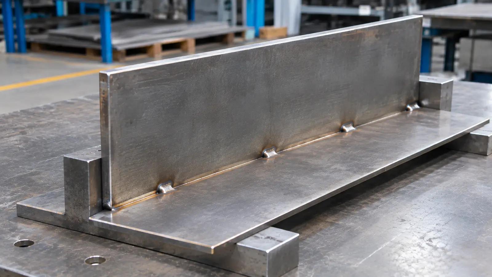
A useful fixture sets the right starting geometry and keeps access to the required welds. It should also allow safe removal of the finished part. A clamp that makes a part appear perfect during welding has not proved that the part will stay in tolerance after release.
Tack weld positions should help maintain joint gaps and alignment without causing an uneven pull of their own. The number, size and placement of tacks depend on the part and approved procedure. Clamps, strongbacks and temporary supports may reduce movement, but too much restraint can raise residual stress or crack risk in sensitive materials.
In some designs, a controlled pre-set can help. This means placing a part slightly away from its final target shape so expected shrinkage brings it into alignment. The offset must be established by engineering assessment and representative trials, not guessed from a general online rule.
The earlier the assembly is reviewed, the more freedom there may be to change weld placement, stiffness and fixture access. Meco’s R&D engineering page gives context on design and production planning.
How can manufacturers verify distortion control on finished parts?
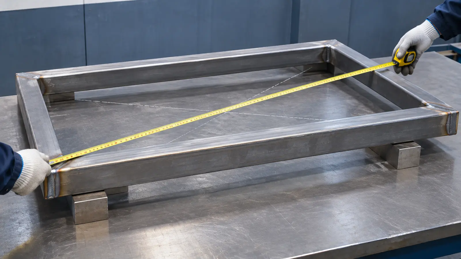
Check a representative first-off part using the intended material, fixture, weld sequence and approved conditions. Record its dimensions before welding, after cooling and after release from restraint. A single measurement taken while the part is clamped does not establish the free-state result.
Measure the features that matter to the drawing: diagonals for frame squareness, flatness for mounting faces, straightness for rails and position for holes or brackets. Use suitable gauges, a surface plate, fixtures or coordinate measurement as the project requires.
Where the assembly later receives machining, coating or mechanical assembly, consider whether those steps can hide or worsen a fit problem. A welded frame can look straight on a bench but still interfere with installed rails or covers.
For service-level context rather than a process comparison, Meco describes gas shielded welding and laser welding. The distortion controls in this article must still be selected for the particular design, not by assuming one named process always gives the best result.
Once the trial part meets both weld quality and dimensional criteria, record the chosen sequence, fixturing and inspection points so later production can repeat them.
What if a welded part is already distorted?
Do not force a part back into shape or apply unplanned heat just because a dimension is out of tolerance. First identify the affected feature, the measured amount of change and any weld or material concerns. Then compare the result with the approved acceptance rules.
Some parts may be suitable for controlled mechanical straightening, local heating or a defined rework process. Those methods can change residual stress and local material properties. They need an engineering-approved plan, suitable equipment and inspection afterward. A sensitive or critical component may need a different disposition.
Grinding a weld smaller or adding another weld to “pull it back” is not a universal repair. Either action can change weld integrity or create new distortion. The decision may be to rework, remake or accept the part under an authorized deviation, depending on the project rules.
What information helps Meco review a distortion concern?
Share a drawing that marks the welds and controlled dimensions, along with material grade, thickness, quantity and expected loading. Include the joint design, weld size, order of operations and available fixture photographs. Measurements before welding and after cooling are especially helpful.
If the issue appeared after a change, mention a new fixture, different joint gap, altered weld order or revised assembly method. That makes it easier to discuss a practical check rather than simply requesting a lower-temperature weld.
Meco can review fabrication and assembly planning with the wider manufacturing requirements in view. The final acceptability of welds and dimensions remains governed by the project drawing, procedure and applicable codes.
Plan Welded Parts That Fit
Share your drawing, weld locations, required tolerances and production quantity. Meco can discuss weld placement, fabrication sequence, fixturing and the checks needed before assembly.
- Drawing, material grade, thickness and quantity
- Weld size, joint arrangement and planned sequence
- Flatness, hole position, fit and other critical dimensions
- Measurements or photographs showing movement after cooling
References and sources
- TWI. Distortion: Types and causes. Distortion: Types and causes.
- TWI. Distortion: Prevention by design. Distortion: Prevention by design.
- TWI. Distortion control: Prevention by fabrication techniques. Distortion control: Prevention by fabrication techniques.
- TWI. Distortion: Prevention by pre-setting, pre-bending or use of restraint. Distortion: Prevention by pre-setting, pre-bending or use of restraint.
