
CNC Drilling vs Tapping vs Thread Milling: How to Spec Holes and Threads (2026 Guide)
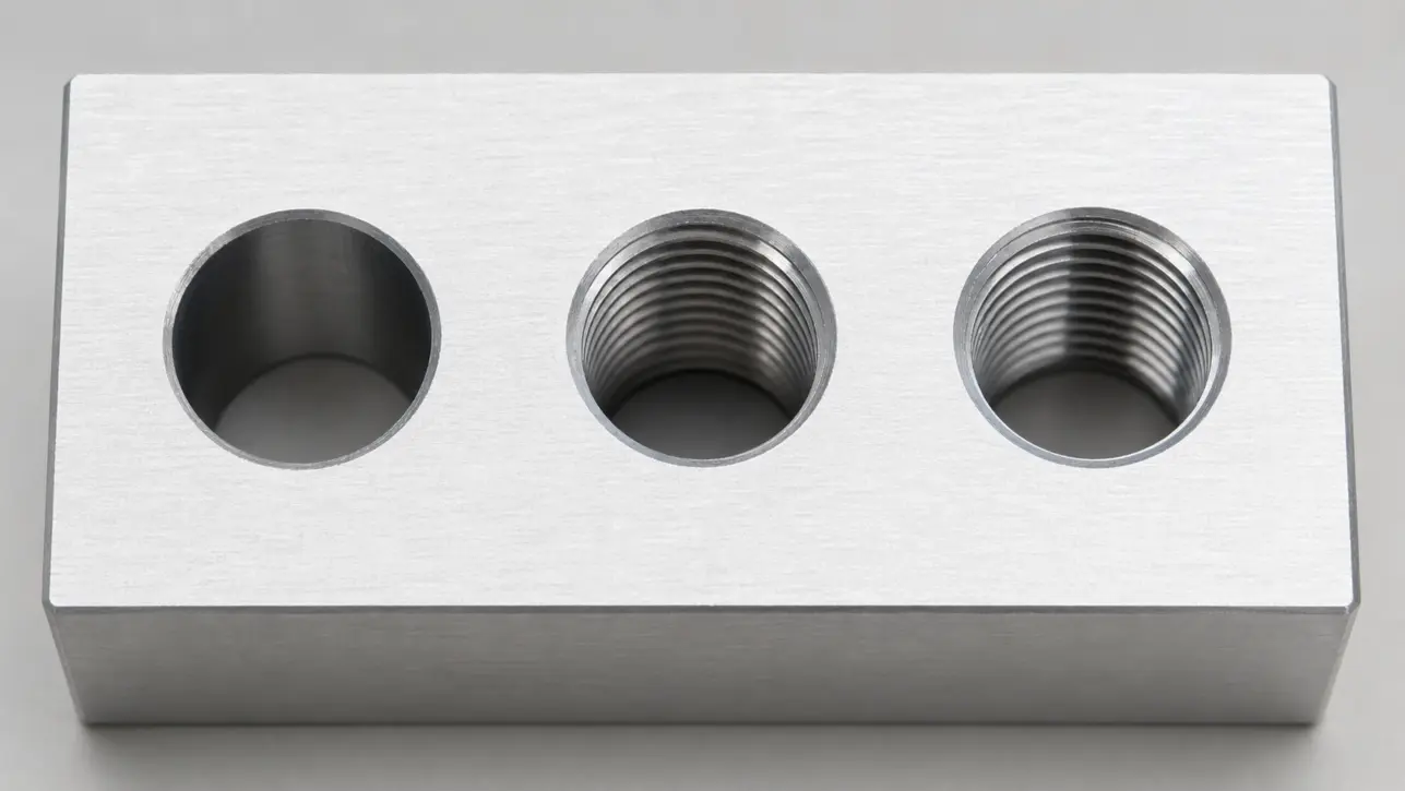
CNC drilling makes the hole. CNC tapping cuts threads inside that hole using a tool shaped like a screw. Thread milling cuts threads using a small rotating cutter that spirals around the hole. Drilling comes first. Tapping and thread milling are two different ways to add threads after the hole exists.
That's the short answer. But if you're an engineer spec'ing a part, a sourcing manager comparing quotes, or a designer trying to figure out what to put on a drawing, you need more than a one-liner. The wrong choice between tapping and thread milling can cost you broken tools, scrapped parts, or threads that don't meet spec.
This guide walks through all three processes in plain English. We'll cover when each one wins, what tolerances you can hold, how to pick the right tap drill size, real cost-per-hole numbers, and the design rules that keep your parts cheap and your machinist happy. By the end, you'll be able to spec holes and threads with confidence.
What's the Real Difference Between Drilling, Tapping, and Thread Milling?
CNC drilling creates a smooth round hole using a rotating drill bit fed straight down into the material. CNC tapping cuts internal threads inside an existing hole using a tap, a tool that looks like a hardened screw with cutting flutes. Thread milling uses a small toothed cutter that spirals around inside the hole to cut threads. Drilling is always first. Tapping and thread milling are two different paths to the same threaded result.
Think of it as a three-step model we use at Meco: Hole, Thread, Verify. You can't skip steps and you can't reorder them.
- Hole: Drilling creates the starting hole at the correct diameter (the tap drill size).
- Thread: Tapping or thread milling adds the internal threads.
- Verify: Inspection confirms the thread fits the bolt or fastener that needs to go in.
Drilling and tapping are often combined on the same CNC machine in one program. This is why "drill-and-tap centers" are a common machine type in production shops, and why most sourcing quotes treat the two operations as a combined cost. Thread milling is a different beast. More flexible, but slower per hole. The rest of this guide explains when each wins.
CNC Drilling Explained: Making the Hole First
CNC drilling is the most common machining operation on the planet. A rotating drill bit is fed into the material at a controlled speed. It removes material as chips and leaves a round hole behind. Simple in theory, but a lot can go wrong.
On a CNC mill or machining center, drilling is programmed using G-codes like G81 (basic drill cycle), G82 (drill with dwell), and G83 (peck drilling cycle). Modern CNC drilling services can hold positional accuracy to ±0.01 mm and produce thousands of identical holes per shift.
The drill itself matters. Standard twist drills work for most holes up to about 5 times the drill diameter deep. Beyond that, you need different tooling and a different approach.
Peck Drilling and Deep Hole Drilling
Peck drilling is a technique where the drill plunges down a short distance, retracts to clear chips, then plunges again. It repeats until the hole reaches full depth. This stops chips from packing inside the flutes and snapping the drill.
The rule of thumb: if your hole depth is more than 3 times the drill diameter, peck drill. The first peck is usually 3 times the drill diameter, then 2 times, then equal to the diameter for the rest of the way.
For deep hole drilling (holes deeper than 10 times the drill diameter), standard twist drills don't cut it. We move to parabolic flute drills, coolant-through carbide drills, or gun drilling. These tools push coolant directly to the cutting edge and evacuate chips up the flutes.
| Hole Depth-to-Diameter Ratio | Recommended Approach | Notes |
|---|---|---|
| Up to 3:1 | Standard twist drill, single plunge | Easiest case. Use proper feed and speed. |
| 3:1 to 5:1 | Peck drilling (G83) | Clears chips, prevents drill snap. |
| 5:1 to 10:1 | Parabolic flute or coolant-through carbide | Better chip evacuation, higher feed rates. |
| 10:1 and beyond | Gun drilling or BTA drilling | Specialized deep hole drilling tooling required. |
Blind Holes vs Through Holes
A through hole goes all the way through the part. A blind hole stops at a set depth inside the material. The difference matters more than you'd think.
Through holes are easier. Chips fall out the bottom. Drills can run faster. Tapping is more forgiving because the tap can run past the bottom of the part.
Blind holes trap chips. The drill has nowhere to evacuate material at the bottom of the hole. The hole bottom is usually a 118-degree point left by the drill, not flat. If you need a flat bottom, you need a secondary operation with an end mill.
For tapping, blind holes are where most taps break. We'll come back to this.
CNC Tapping Explained: Cutting Threads Inside the Hole
CNC tapping uses a tool called a tap to cut internal threads. A tap looks like a hardened screw with flutes (grooves) that act as cutting edges. As the tap rotates and feeds into the hole at exactly the right speed, it cuts threads matching the tap's profile.
Tapping is fast. A typical M6 thread takes about 1 to 2 seconds per hole on a modern machining center. That speed is why CNC tapping is the default choice for high-volume production parts with threaded holes.
Before tapping, you have to drill the hole at the right size. Too small and the tap breaks. Too big and the threads are weak. The correct hole diameter is called the tap drill size, and it varies by thread.
For a common M6 x 1.0 thread, the tap drill size is 5.0 mm. For a 1/4-20 UNC thread, the tap drill size is #7 (0.201 inch). Every thread has its own tap drill size, listed in standard charts.
What Is Rigid Tapping?
Rigid tapping is when the CNC machine's spindle rotation is perfectly synchronized with its Z-axis feed motion. The tap moves down exactly one thread pitch for every spindle revolution. No mechanical tension. No floating tap holder.
The old way (called tension-compression tapping) used a spring-loaded holder to handle small mismatches between spindle speed and feed. It worked, but it was slow and less precise.
Modern CNC machines almost all support rigid tapping. The programming uses G84 (or M29 + G84 on Fanuc controls). Rigid tapping is faster, more accurate, and allows higher RPM. It's the standard for production work today.
Rigid tapping also enables tap reversal at the bottom of the hole without breaking the tap. The spindle decelerates, stops, and reverses with the Z-axis in sync. This is critical for blind hole tapping.
Why Taps Break (And How to Prevent It)
Tap breakage is the most common headache in CNC tapping. A broken tap stuck in a part is a nightmare to remove and often scraps the whole workpiece.
Taps break for predictable reasons. According to EMUGE-FRANKEN's tap breakage prevention guide, the top causes are wrong tap drill size, poor coolant delivery, chip packing in blind holes, and worn taps run past their service life.
How to Stop Breaking Taps
1. Verify your tap drill size against the standard chart before running the first part. A 0.1 mm undersize hole is the #1 cause of tap breakage.
2. Use the right tap geometry for the hole type. Spiral point (gun nose) taps push chips forward, ideal for through holes. Spiral flute taps pull chips back out, ideal for blind holes.
3. Flood the hole with coolant or use through-spindle coolant. Dry tapping kills taps and threads alike.
4. Drill blind holes deeper than the thread depth. Add at least 3 thread pitches of clearance at the bottom for chips to collect.
5. Track tap life. Replace taps on a scheduled cycle, not after they break. A broken tap costs 50 times more than a fresh one.

Thread Milling Explained: The Flexible Alternative
Thread milling cuts threads using a small rotating cutter that moves in a helical path inside the hole. The cutter has teeth shaped to match the thread profile. As the spindle rotates the cutter and the machine moves it in a spiral motion, threads get cut into the hole wall.
Thread milling needs three-axis simultaneous motion. That's why it only runs on a real CNC machining center, not a drill press or manual mill. If you have CNC milling capability, you can thread mill.
Here's where thread milling beats tapping:
- One tool, many sizes. A single thread mill can cut multiple thread sizes of the same pitch. A tap only cuts one size.
- Better for hard materials. Stainless steel, Inconel, and titanium are tough on taps. Thread mills handle them better because each tooth takes a smaller bite.
- Broken tool recovery. If a thread mill breaks, the workpiece can usually be saved. A broken tap stuck in a part often means scrap.
- Tighter tolerance control. Thread milling lets you adjust the cutter path to control thread fit class precisely.
- Closer to part edges. Thread mills work near thin walls or edges where a tap would crack the material.
So why doesn't everyone thread mill? Speed and cost. A tap finishes an M6 hole in about 1.5 seconds. A thread mill takes 6 to 10 seconds for the same hole. For a part with 50 threaded holes, that's an extra 5 to 7 minutes per part. Across 10,000 parts, that's serious money.
The other downside: thread mills cost 5 to 20 times more than taps upfront. For low-volume work, the tool cost is hard to justify.
Why Tapping Is Still Winning (Despite the Thread Milling Hype)
If you read the trade press lately, thread milling sounds like the only answer. Better tolerances. No broken taps. Universal tooling. All true. But here's what gets left out of the marketing: in the vast majority of production work we see at Meco, tapping is still the right call. Here are the three scenarios where it wins decisively.
Scenario 1: High-volume parts in soft materials. A run of 50,000 aluminum brackets with M6 threads is tapping territory, full stop. At 1.5 seconds per hole tapped versus 8 seconds thread milled, that's a difference of 90 hours of machine time across the run. At a typical $75 per hour shop rate, you've spent $6,750 chasing a tolerance benefit you didn't need.
Scenario 2: Standard thread sizes with standard fit classes. M6-6H or 1/4-20 UNC-2B is what 95% of fasteners use. Taps cut these exact sizes at the exact required class. There's nothing to "control" with a thread mill, because the tap is already correct out of the box. The flexibility of thread milling becomes a non-feature when you don't need it.
Scenario 3: Programs already validated under IATF 16949 or similar quality systems. If your part is in a PPAP-approved process running rigid tapping, switching to thread milling means re-validating the process, updating control plans, and re-running FAIR. That's weeks of work and real cost for zero functional improvement.
The honest take: thread milling is a precision tool that belongs in your back pocket for hard materials, large threads, edge cases, and high-value parts. Tapping is the workhorse that ships the other 80% of production. Use both. Don't replace one with the other on principle.
CNC Drilling vs Tapping vs Thread Milling: Process Comparison Table
Here's how all three processes stack up on the criteria that matter most when you're choosing a method, including rough cost-per-hole estimates based on typical production shop rates. Cost ranges assume mid-volume production in standard materials. For deeper pricing context, our CNC machine costs guide breaks down the full picture.
| Criteria | CNC Drilling | CNC Tapping | Thread Milling |
|---|---|---|---|
| Purpose | Create the hole | Cut internal threads | Cut internal threads |
| Speed per hole | Very fast (under 1 sec) | Fast (1-2 sec for M6) | Slower (6-10 sec for M6) |
| Typical cost per hole (production volume) | $0.02 - $0.08 | $0.05 - $0.15 | $0.40 - $0.80 |
| Tool cost | Low ($5 - $30) | Low ($10 - $50) | High ($100 - $400) |
| Tolerance control | ±0.01 mm typical | Fixed by tap spec | Adjustable via toolpath |
| Best for hard materials | Yes with right drill | Difficult | Excellent |
| Blind holes | Yes | Risky (chip packing) | Excellent |
| Risk of broken tool scrapping part | Low | High | Low |
| Volume sweet spot | Any volume | Medium to very high | Low to medium |
Quick Decision Rule
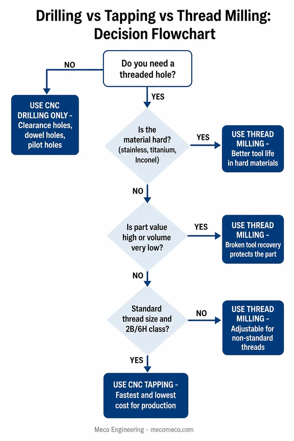
Use tapping when: production volume is high, the material is mild steel or aluminum, and threads are common sizes (M6, M8, 1/4-20).
Use thread milling when: the material is hard (stainless, titanium, Inconel), the threads are large or non-standard, you need tight tolerance control, or the part value is too high to risk a broken tap.
Use drilling alone when: you just need a clearance hole, dowel hole, or pilot hole with no threads.
Hole Tolerancing: Standards and Achievable Specs
Hole tolerancing tells the machinist how much variation is acceptable between the designed hole size and the actual hole. Without tolerances, you're hoping the shop guesses right. With tolerances, you're specifying exactly what fits and what doesn't.
The two main standards used in machining are ISO 286 (limits and fits for shafts and holes) and ISO 2768 (general tolerances). For most parts, ISO 2768 medium class (m) covers it, calling for around ±0.1 mm on holes from 6 to 30 mm. Precision work calls for ISO 2768 fine class (f), which tightens that to about ±0.05 mm.
For very tight fits between a hole and a shaft (like a bearing seat or dowel pin), engineers use ISO 286 fit codes like H7/h6 or H7/p6. These specify deviations in microns. A 10 mm H7 hole, for example, must measure between 10.000 mm and 10.015 mm. That's how tight bearing seats get spec'd on production drawings.
At Meco, our standard CNC machining capability holds ±0.01 mm on critical features, verified with calibrated CMM equipment (±0.002 mm measurement precision). For high-precision aerospace and automotive programs running under our IATF 16949:2016 quality system, we use SPC and FAIR documentation to prove tolerances are met across the production run.
From the Floor: A Real Cost-Saving DFM Catch
We recently quoted an automotive bracket where the original drawing called for thread milling on 24 M8 holes. The customer assumed thread milling was "safer" for production. After DFM review, our engineers recommended rigid tapping instead, since the material was 6061 aluminum and the thread class was a standard 6H. The result: a 23% lower part cost across the program, the same thread class verified at First Article Inspection, and zero broken taps across the first 12,000 parts. Sometimes the right answer is the simpler one.

Thread Classes Explained: UNC, UNF, and Metric (6H/6g)
Once you've decided to add threads, you need to spec the thread class. Thread classes define how tight or loose the fit is between the internal threads (in your part) and the external threads (on the bolt or screw).
In North America, threads follow ASME B1.1 for inch (Unified) threads. The full standard is published at ASME B1.1 Unified Inch Screw Threads. Internationally, metric threads follow ISO 965-1.
Inch threads come in two main series: UNC (Unified Coarse) and UNF (Unified Fine). UNC has fewer threads per inch and is the default for most general fastening. UNF has more threads per inch and is used where vibration resistance or fine adjustment is needed.
Each thread also has a class number that defines fit. For internal threads (holes), the classes are 1B, 2B, and 3B. For external threads (bolts), they're 1A, 2A, and 3A. Higher number means tighter fit. Class 2B is the standard for most production work. Class 3B is for precision applications.
Metric thread classes work differently. Internal thread classes use H designations (6H is standard). External classes use g or h designations (6g is standard for bolts).
| Thread System | Standard Class (Internal) | Standard Class (External) | Typical Application |
|---|---|---|---|
| UNC (Inch Coarse) | 2B | 2A | General fastening, brackets, frames |
| UNF (Inch Fine) | 2B | 2A | Vibration-prone joints, fine adjustment |
| Precision Inch | 3B | 3A | Aerospace, instruments, gauges |
| Metric (ISO 965) | 6H | 6g | Standard global production |
| Metric Precision | 4H or 5H | 4h or 5h | High-precision metric assemblies |
For the vast majority of production parts we see, spec'ing M6x1.0 - 6H (metric) or 1/4-20 UNC - 2B (inch) is the right call. Going tighter than that adds cost without adding function. We see this mistake regularly: drawings that call for 3B threads on a non-critical bracket, which forces thread milling instead of tapping and adds 15% or more to the part cost for no real benefit.
DFM Rules: How to Spec Holes and Threads on Your Drawing
Design for Manufacturability (DFM) is about giving your machinist the best chance to make a good part the first time. Bad hole and thread specs are one of the most common reasons for rework. These rules will keep your drawings clean and your parts cheap.
1. Use standard thread sizes whenever possible. M3, M4, M5, M6, M8, M10, M12 in metric. 4-40, 6-32, 8-32, 10-32, 1/4-20, 3/8-16 in inch. Non-standard sizes (M3.5, 5/16-18) cost more because tools and gauges aren't kept in stock.
2. Match thread class to function. 2B (inch) or 6H (metric) covers most parts. Don't spec 3B unless the assembly truly needs it.
3. Drill blind holes deeper than the thread depth. A useful rule is thread depth plus 3 thread pitches of clearance at the bottom. This gives chips somewhere to go during tapping.
4. Keep thread depth reasonable. For most materials, useful thread engagement is 1 to 1.5 times the thread diameter. Going deeper than 2x is wasted effort because the first few threads carry most of the load.
5. Avoid threads near edges or thin walls. Minimum edge distance is at least 1.5 times the thread diameter to prevent cracking. If you must put a thread near an edge, spec thread milling.
6. Note the thread class and depth clearly. A complete callout looks like: M6x1.0 - 6H - THRU or M6x1.0 - 6H - 12 DEEP. Don't leave depth ambiguous on blind holes.
7. Specify positional tolerance for hole patterns. Use GD&T position tolerance on hole patterns rather than relying on linear dimensions. Position tolerance gives the machinist a circular tolerance zone, which matches how holes actually deviate.
8. Add a chamfer to threaded holes. A 0.5 mm x 45 degree chamfer at the entry helps the bolt start cleanly and protects the first thread from damage. It costs almost nothing to machine and prevents assembly headaches.
9. Ask for DFM feedback before releasing drawings. A quick review by an experienced machinist catches issues like unrealistic thread depths, incompatible thread classes, or hole positions too close to features. Meco includes DFM feedback with every quote.
10. Plan for inspection. Threads are verified with go/no-go gauges. Make sure your callouts match standard gauge availability. Custom thread sizes require custom gauges, which can take weeks to manufacture.
Sample Drawing Callouts (And What Each Symbol Means)
A clean callout tells the shop everything they need in one line. A messy callout creates questions, delays, and quoting errors. Here are three real-world examples of how to write hole and thread specs correctly, with each part of the callout decoded.
Example 1: A standard blind threaded hole in aluminum.
M6x1.0 - 6H ↧ 12, ⌀5.0 ↧ 15
- M6x1.0 = metric thread, 6 mm nominal diameter, 1.0 mm pitch
- 6H = standard metric internal thread class
- ↧ 12 = thread depth of 12 mm (the "downward arrow" symbol means depth)
- ⌀5.0 = drill diameter of 5.0 mm (the tap drill size for M6x1.0)
- ↧ 15 = drill depth of 15 mm (3 mm deeper than thread depth, giving chip clearance)
Example 2: A standard through threaded hole in inch units.
1/4-20 UNC - 2B ▽ THRU
- 1/4-20 = 1/4 inch nominal diameter, 20 threads per inch
- UNC = Unified National Coarse thread series
- 2B = standard internal thread fit class
- ▽ THRU = countersink/chamfer indicator, hole goes all the way through the part
Example 3: A precision dowel pin hole with positional tolerance.
⌀6.000 +0.012/+0.000 (H7) ↧ 20 | ⌖ ⌀0.05 Ⓜ A B C
- ⌀6.000 +0.012/+0.000 = 6 mm hole that must measure between 6.000 mm and 6.012 mm
- (H7) = the ISO 286 fit code that matches this tolerance range
- ↧ 20 = depth of 20 mm
- ⌖ ⌀0.05 = positional tolerance, the hole center must be within a 0.05 mm diameter circle of its true location
- Ⓜ = at Maximum Material Condition (allows bonus tolerance when the hole is at its smallest)
- A B C = the datum references that define the part's coordinate system
These three callouts cover roughly 80% of the hole and thread features you'll ever spec. Get them right on your drawings and the rest of production gets easier.
Combining drilling, tapping, and thread milling under one roof, with quality control built in from the start, is exactly what a turnkey machining partner is for. To see how this fits together on real production parts (and how it compares to typical shop pricing), our breakdown of CNC machine costs is a good next read.
Frequently Asked Questions About CNC Drilling, Tapping, and Thread Milling
What is the difference between CNC drilling and tapping?
CNC drilling creates a smooth round hole using a rotating drill bit. CNC tapping cuts internal threads inside an existing hole using a tap, which is a hardened tool shaped like a screw. Drilling always comes first. Tapping turns a plain hole into a threaded hole that a bolt can screw into. The two operations are often run back-to-back in the same CNC program on a drill-and-tap center.
Can you tap a hole without drilling first?
No. Tapping requires a pre-existing hole at the correct tap drill size, called the minor diameter. Trying to tap solid material would snap the tap on the first revolution because the tool isn't designed to remove that much material. The drill must be sized so the tap only cuts away the thread material, not the bulk of the hole. For an M6 x 1.0 thread, that means drilling a 5.0 mm hole first, then tapping.
What size drill bit do you need before tapping?
The correct drill size is called the tap drill size and depends on the thread you're cutting. For M6 x 1.0 threads, the tap drill size is 5.0 mm. For 1/4-20 UNC threads, it's #7 (0.201 inch). Every thread size has a specific tap drill size listed in standard charts, and using the wrong size is the most common cause of broken taps.
Is thread milling stronger than tapping?
No. The threads produced by both processes have the same strength when the thread class and depth are equal. Thread strength is determined by the thread profile and the material around it, not the cutting method. The real advantages of thread milling are tolerance control, the ability to recover a broken tool without scrapping the part, and better performance in hard materials like stainless steel and titanium. For raw thread strength alone, tapping and thread milling are equal.
When should you use thread milling instead of tapping?
Use thread milling when the material is hard (stainless steel, titanium, Inconel), when the part value is too high to risk a broken tap, when threads need tight tolerance control, when threads are large or non-standard, or when threads are near a thin wall or edge. For high-volume production in soft materials with standard thread sizes, tapping is faster and cheaper.
Why do taps break in blind holes?
Taps break in blind holes because chips have nowhere to escape. They pack into the bottom of the hole, jam the tap, and snap it. Prevention requires drilling the hole deeper than the thread depth (at least 3 thread pitches of clearance), using spiral flute taps that pull chips back out, and flooding the hole with coolant during tapping.
What is rigid tapping on a CNC machine?
Rigid tapping is a mode where the CNC machine synchronizes its spindle rotation exactly with its Z-axis feed motion, so the tap moves down one thread pitch per spindle revolution with no mechanical tension. It's programmed using G84 (with M29 on Fanuc controls). Rigid tapping is faster, more accurate, and allows higher RPM than older tension-compression tapping methods.
What tolerances can CNC drilling and tapping hold?
Standard CNC drilling holds positional accuracy around ±0.01 mm and hole diameter tolerance per ISO 2768 medium class (±0.1 mm on holes 6 to 30 mm). Precision drilling can hold ISO 2768 fine class (±0.05 mm) or ISO 286 fit codes like H7 for bearing seats. CNC tapping holds the thread class spec (typically 2B or 6H), verified with go/no-go thread gauges.
Free DFM Review: We'll Flag Every Hole and Thread That's Costing You Money
Most drawings we quote have at least one hole or thread spec driving cost the engineer never intended. A 3B class on a non-critical bracket. A blind hole drilled too shallow for clean tapping. Thread milling spec'd on a part where rigid tapping would cut cycle time by 80%. These small mistakes add up to 15-30% wasted on every part you ship.
Send us your drawing. We'll mark it up and send it back. Our engineers will flag every callout that adds cost without adding function, with specific recommendations for what to change and how much you'll save. No obligation. No sales pitch. Just an honest engineering review from a team that's done this for 30+ years.
Here's what makes our DFM review different from a typical quote:
- Marked-Up Drawing Returned: Every hole, thread, and tolerance reviewed line by line. Suggested changes annotated directly on your PDF.
- Quantified Cost Impact: We tell you exactly which changes save how much, so you can decide what to accept and what to keep.
- IATF 16949:2016 Certified Discipline: The same process discipline we apply to automotive production. 99.99% quality rate. 99.8% on-time delivery.
- 40+ Processes Under One Roof: CNC drilling, CNC tapping, thread milling, 3/4/5-axis milling, turning, surface finishing, and assembly. One partner, one accountable workflow.
- ±0.01 mm Capability: Verified with calibrated CMM equipment. Full FAIR and PPAP documentation available for regulated industries.
- Quote Returned in Under 24 Hours: DFM review and pricing delivered the next business day, every time.
If we find ways to save you money on tooling, cycle time, or material, you keep every dollar of the savings. We get a happy customer who comes back for the next program. That's the trade we're making.
Upload your drawings and let our engineers do what they do best. The review costs you nothing. The mistakes you're shipping today are costing you plenty.
Request Your Free DFM Review