What Causes Die Casting Defects and How to Prevent Them (2026 Guide)
Die casting defects are flaws in a cast part caused by problems with metal flow, gas, temperature, pressure, or die wear. The most common ones are porosity (tiny voids inside the part), cold shuts (where two metal streams fail to fuse), flash (excess metal at the parting line), die soldering (molten metal sticking to the die), and blistering on aluminum parts. Most defects are preventable with the right gating, venting, temperature control, and design review before tooling is cut.
If you're an engineer or sourcing manager looking at a casting that doesn't pass inspection, you want two things fast: what caused it, and how to stop it from happening again. This guide gives you both, in plain English, with the same playbook our team uses in our IATF 16949:2016 certified die casting cells every day.
Key Takeaways
- The 8 most common defects are gas porosity, shrinkage porosity, cold shuts, flash, die soldering, blistering, misruns, and flow marks. Each has a known cause and a known fix.
- Porosity is the #1 problem. Round voids = gas (fix the die). Jagged voids = shrinkage (fix the design or process).
- Most defects come from process control, not bad luck. Venting, gating, temperature, and die wear cause the majority of rejects we see.
- DFM stops most defects before they start. A 30-minute design review before steel is cut saves weeks of rework after.
- Use the SCAN framework (Surface, Cavity, Alignment, NDT) to catch defects before they ship to a customer.
We'll walk through the eight most common die casting defects, dig deep into die casting porosity (the #1 problem), break down cold shuts, flash, soldering, and blistering, and then hand you a quick-reference troubleshooting matrix you can use on the shop floor. We'll also share the SCAN framework our engineers use to inspect every casting before it ships.
What Are Die Casting Defects?
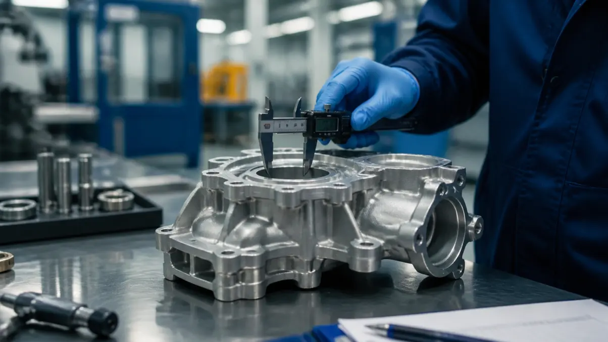
Die casting defects are any features in a finished cast part that fall outside the agreed quality spec. They show up on the surface (flash, blisters, flow lines), inside the part (porosity, shrinkage voids), or as dimensional errors (warpage, short shots, missing features).
Why do they happen? Die casting is a high-speed, high-pressure process. Molten aluminum, zinc, or magnesium gets shot into a steel die at speeds over 100 feet per second and held under pressures up to 30,000 psi. A lot can go wrong in that fraction of a second. Gas can get trapped. Metal can cool too fast. Dies wear. Vents clog. Even tiny shifts in any of these variables show up as defects.
The good news: most defects have a known cause and a known fix. The North American Die Casting Association (NADCA) publishes detailed acceptance criteria and design rules that most of the industry follows. Alloy selection is also covered by ASTM B85, the standard specification for aluminum-alloy die castings. Pairing these references with strong process control catches the vast majority of problems before they reach a customer.
The Three Defect Families
It helps to think of die casting defects in three buckets: filling defects (cold shuts, misruns, flow marks) caused by metal that didn't reach or fuse correctly, solidification defects (shrinkage porosity, cracks) caused by how the metal cooled, and process defects (gas porosity, flash, soldering, blistering) caused by the machine, die, or lubrication. Knowing the family narrows your fix in seconds.
The 8 Most Common Die Casting Defects
Here are the eight defects we see most often across aluminum, zinc, and magnesium die casting programs. This table is the fastest way to spot what you're looking at and where to start.
| Defect | What It Looks Like | Main Root Cause | First Fix to Try |
|---|---|---|---|
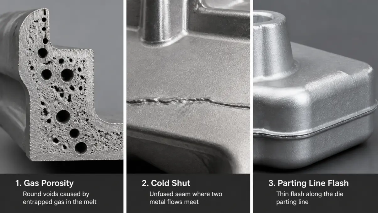
| Gas porosity | Round, smooth-walled internal voids | Trapped air or steam during the shot | Improve venting; add vacuum assist |
| Shrinkage porosity | Irregular, jagged internal voids | Metal shrinks as it cools with no feed | Increase intensification pressure; rebalance wall thickness |
| Cold shut | Visible seam or line where metal didn't fuse | Low metal temperature or slow fill | Raise pour temperature; speed up fill |
| Flash | Thin fins of metal at the parting line | Worn die, low clamp force, or pressure spike | Check die wear; verify machine tonnage |
| Die soldering | Aluminum sticking to the die surface | Die surface too hot; lubricant breakdown | Lower die temp; reapply release agent |
| Blistering | Raised bubbles on the surface, often after heat | Subsurface gas pockets expanding | Cut gas porosity at the source (vent, vacuum) |
| Misrun / short shot | Part is incomplete; features missing | Not enough metal, or it froze too soon | Increase shot volume; raise die temperature |
| Flow marks | Visible streaks or wavy lines on the surface | Turbulent or interrupted metal flow | Adjust gating; tune injection profile |
The next sections go deeper into the four that cause the most rejections in real production: porosity, cold shuts, flash, and soldering. Blistering gets its own section too since it's specific to aluminum and often misdiagnosed.
Porosity in Die Casting: The #1 Problem
Porosity is the most common defect family in die casting and the one that causes the most field failures. Porosity means tiny voids or pockets inside the metal. Those voids weaken the part, make it leak under pressure, and prevent successful heat treatment or welding.
There are two main types: gas porosity and shrinkage porosity. They look different, come from different causes, and need different fixes. Confusing the two is the fastest way to waste a week chasing the wrong problem.
What Is Gas Porosity?
Gas porosity is caused by air, steam, or hydrogen getting trapped in the molten metal during the shot. When the metal solidifies, those gas pockets stay behind as smooth, round voids. According to FLOW-3D's gas porosity guide, trapped air from turbulent fill is usually the biggest single source.
Common causes include poor die venting, fast fill speeds that fold air into the metal, wet die lubricant flashing into steam, and hydrogen pickup from damp aluminum. The fix is almost always at the die: better vents, optimized gating, and in tough cases, vacuum-assisted die casting to pull the air out before the metal hits.
What Is Shrinkage Porosity?
Shrinkage porosity is caused by the metal itself. Every liquid metal shrinks a few percent as it freezes. If the casting doesn't have a clear path to feed fresh molten metal into the section that's solidifying last, a void forms there. Shrinkage voids are usually jagged and irregular, not smooth and round.
This is mostly a design and process problem. Thick sections next to thin walls, sharp corners, and bosses without proper risers are classic causes. Fixes include increasing the intensification pressure (the second-stage squeeze the machine applies right after the cavity fills, which forces extra metal into the part to make up for shrinkage), rebalancing wall thickness in the design, and improving die cooling so the part freezes in the right order.
Gas Porosity vs. Shrinkage Porosity
| Feature | Gas Porosity | Shrinkage Porosity |
|---|---|---|
| Void shape | Round, smooth walls | Jagged, irregular, often tree-like |
| Location | Anywhere; often near surface | Thickest sections; last to freeze |
| Root cause | Trapped gas (air, steam, hydrogen) | No metal feed during solidification |
| Process fix | Vents, vacuum, lower fill turbulence | Higher intensification pressure, better cooling |
| Design fix | Gate redesign; flow simulation | Uniform wall thickness; remove hot spots |
How Do You Fix Porosity in Die Castings?
In our experience, the majority of porosity issues we see on customer programs trace back to venting and gating, not alloy chemistry or operator error. Fix the die, and you fix most of the parts.
Here's the practical order we use when we troubleshoot porosity on a customer program:
- Cut a section. Look at the void shape under magnification. Round = gas. Jagged = shrinkage. This single check saves days.
- Check venting and overflow design. Most older dies are under-vented. Adding chill vents or upgrading to a vacuum system often solves gas porosity in one trial.
- Review the shot profile. Slow-shot too fast and you fold air into the metal. Too slow and you get cold shuts. The sweet spot is alloy and part specific.
- For finished parts, vacuum impregnation can seal porosity in non-structural applications (think pressure-tight housings). It doesn't fix the root cause, but it can save a batch.
- For shrinkage, raise intensification pressure first, then look at the design. Uniform walls and rounded transitions beat any process tweak.
What Is a Cold Shut and How Do You Prevent It?
A cold shut is a visible seam, crack, or line on a casting where two streams of molten metal met but didn't fully fuse together. Picture two rivers flowing into a lake from different sides. If the water is hot enough, they blend smoothly. If it's cooled too much, you see a clear line where they meet. Same thing with molten aluminum.
Cold shuts almost always come from one of three things: metal temperature too low, fill speed too slow, or fill paths too long. The metal at the leading edge of each stream loses heat as it travels. By the time the streams meet, they've formed a thin oxide skin and can't fuse.
To prevent cold shuts, raise the pour temperature within the alloy's safe window, increase the gate velocity so metal arrives hot, shorten flow distances with better gating, and improve die preheat so the metal isn't shocked the moment it touches the cavity. A flow simulation done before the die is cut catches most cold shut problems on paper, before you spend money on steel.
What Causes Die Casting Flash and How Do You Stop It?
Die casting flash is the thin fin of excess metal that squeezes out between the two halves of the die during the shot. You usually see it along the parting line, around ejector pins, or near slide interfaces. A little flash is normal and gets trimmed off. Heavy or repeated flash means something is wrong.
The three usual suspects are die wear, low clamp force, and pressure spikes. As a die ages, the parting surfaces erode. Even a few thousandths of a gap is enough for high-pressure molten metal to push through. If your machine isn't applying enough tonnage to hold the die fully closed, you'll also see flash. Same story if the metal pressure spikes above what the machine can resist.
To stop parting line flash, inspect the die for wear and recondition the parting surface. Verify clamp tonnage against the projected area of the casting times the metal pressure. Optimize the shot profile so you don't overshoot intensification. And if flash keeps coming back to the same spot, that's a strong signal to relocate a gate or vent in the next die revision. The NADCA parting line guide covers acceptable flash criteria in detail.
Die Soldering: Why It Happens and How to Fix It
Die soldering is when molten aluminum welds itself to the steel die surface. Tiny bits of casting tear away with the die when the part ejects, leaving rough patches on the part and damaging the die. Left unchecked, soldering destroys die life and ruins surface finish.
The root cause is almost always heat. When the die surface temperature climbs above a critical threshold (around 400°C / 750°F for many aluminum alloys), iron in the die starts reacting with aluminum in the melt. Worn or thin die release coatings make it worse. So does turbulent flow that scrubs lubricant off in high-velocity zones. Detailed mechanism studies, including a widely-cited U.S. Department of Energy report on die soldering, confirm that surface temperature is the dominant variable.
To fix die soldering, get the die temperature back into the safe window with better cooling line layout or higher coolant flow. Reapply or upgrade the release agent. Check that spray timing actually covers the hot zones. In persistent cases, surface-treat the die (nitriding, PVD coatings) to add a barrier between the steel and the aluminum. And for chronic soldering on a single zone, redesigning the gate to reduce velocity at that face usually solves it permanently.
What Causes Blistering in Aluminum Die Castings?
Blistering aluminum die casting parts have raised bubbles or domes on the surface, usually showing up after the part is heat treated, painted, or powder coated. The blister is the surface skin of the casting being pushed outward by a gas pocket trapped just below.
So blistering isn't really its own defect. It's a symptom of subsurface gas porosity that the part survived in the as-cast state but couldn't hide once heat expanded the trapped gas. Blisters most often appear during T6 solution heat treatment, which holds aluminum alloys at roughly 500-540°C (930-1000°F) for several hours. At those temperatures, even a tiny subsurface gas pocket expands enough to push the surface outward. That's why blisters often appear in finishing, not on the casting machine.
The fix is to attack the gas porosity at the source. Better venting, vacuum assist, lower fill turbulence, and tighter control of die lubricant volume all reduce the gas content in the metal. If you have to ship parts you've already cast, screen suspect batches with a quick hot-water immersion test (typically 30-60 seconds in near-boiling water) which can reveal borderline blistering before it shows up in heat treat. Lower the solution heat treat temperature where the spec allows, or use a T5 temper instead of T6 if the mechanical properties still meet the print. Long term, a process audit on the die and shot profile is the real answer.
Die Casting Troubleshooting Quick Reference
Save this matrix. It's the same one our engineers pull up when a customer sends a defect photo. Match the symptom to the most likely cause, try the immediate fix on the next shot, then plan the process change if it keeps coming back.
| Symptom | Most Likely Cause | Immediate Fix | Long-Term Process Change |
|---|---|---|---|
| Round internal voids (X-ray) | Gas porosity from trapped air | Increase venting; reduce spray volume | Add vacuum system; redesign runners |
| Jagged internal voids | Shrinkage during solidification | Raise intensification pressure | Rebalance wall thickness; add cooling |
| Visible seam line on surface | Cold shut | Raise melt temp 10-15°C; speed up fill | Shorten flow paths; flow simulation |
| Thin metal fins at parting line | Die wear or low clamp tonnage | Verify tonnage; trim and inspect die | Recondition parting surface |
| Rough patches where part ejects | Die soldering | Lower die temp; reapply release agent | Surface-treat die; relocate gate |
| Bubbles appear after heat treat | Blistering from subsurface gas | Lower heat treat temperature | Fix gas porosity at the die |
| Part incomplete or features missing | Short shot / misrun | Increase shot volume; raise die temp | Check biscuit thickness; gate sizing |
| Streaks or wavy lines on surface | Flow marks from turbulent fill | Adjust slow-shot velocity | Redesign gate; tune injection profile |
| Warpage or out-of-flatness | Uneven cooling or ejection | Adjust dwell time | Rebalance cooling lines; add ejector pins |
If you'd rather have a second pair of eyes on a defect you can't pin down, send us photos and the part drawing. Our engineering team turns around a defect diagnosis within 24 hours as part of our standard R&D engineering support.
The SCAN Framework: How Our Engineers Inspect Every Casting
After years of fielding defect calls, our team built a simple mental checklist we run on every casting before it ships. We call it SCAN. It stands for Surface, Cavity, Alignment, and NDT. Each letter is one inspection pass that catches a different family of defects.
S - Surface
Visual and tactile check. Look for flash, flow marks, cold shuts, blisters, soldering rough spots, and finish issues. This catches around half of all defects without any equipment beyond good lighting and a sharp eye.
C - Cavity (Internal)
X-ray or cross-section a sample. This is where porosity hides. Round voids = gas. Jagged voids = shrinkage. If you're shipping high-volume or safety-critical parts, set a sampling rate that matches the program's risk level.
A - Alignment (Dimensional)
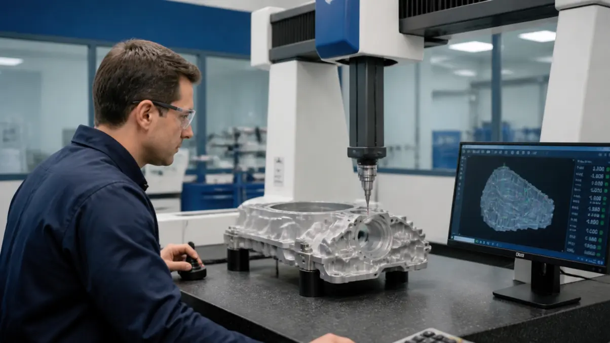
CMM check against the print. Look for warpage, mismatch at the parting line, and tolerance drift on critical features. Our CMMs run to ±0.002 mm precision, which catches the small dimensional shifts that signal die wear before they become reject-level.
N - NDT (Non-Destructive Testing)
For pressure-tight or safety-critical castings, add ultrasonic, dye penetrant, or pressure decay testing. NDT is where you catch the defects that visual and CMM miss, especially for parts heading into automotive or aerospace.
Why a Framework Beats a Checklist
Checklists get long and easy to skip. A four-letter framework forces inspectors to think about why each step exists. SCAN runs in about three minutes per sampled part and has cut our internal escape rate to near-zero on programs that use it consistently.
How DFM Stops Defects Before They Start
The cheapest defect to fix is the one that never gets cast. Design for Manufacturability (DFM) is the engineering review that happens before a die is cut. It's also where most preventable defects get stopped, in our experience.
A good DFM review looks at wall thickness uniformity (uneven walls cause shrinkage), draft angles (too little draft causes ejection damage and soldering), gate location (wrong gates cause cold shuts and flash), parting line position (poor lines cause flash and mismatch), and feature placement relative to the gate (long flow paths cause misruns).
Catching these issues at the CAD stage costs nothing. Catching them after the steel is cut costs weeks and tens of thousands of dollars. That's why every quote we send includes DFM feedback from a real engineer, not just a price. For deeper context on how die casting tooling itself comes together, see our breakdown of the die casting process from start to finish.
Pro Tip: Run DFM Twice
Run a first DFM review at concept, before geometry is locked. Then run a second one right before the die is ordered, after stress and tolerance analysis is done. The double pass catches the issues each review alone would miss.
When to Repair, Rework, or Reject a Defective Casting
Not every defective casting belongs in the scrap bin. The right call depends on the defect type, the part's function, and the spec the customer signed off on. Here's the decision flow our engineers walk through, in order:
- Is the defect on a structural or pressure-tight surface? If yes, go straight to step 5. If no, continue.
- Is it purely cosmetic (light flash, minor flow marks, small mismatch)? If yes, trim, grind, or cover it with surface finishing like powder coating or anodizing. Accept the part.
- Is it light gas porosity in a non-pressure part? If yes, seal it with vacuum impregnation and accept. If no, continue.
- Is the dimensional drift still inside the print tolerance band? If yes, accept. If no, continue.
- Does the defect affect structure, fatigue life, pressure tightness, or safety-critical fit? If yes, reject. Cracks, large shrinkage voids, deep cold shuts, and porosity exceeding NADCA acceptance criteria are not candidates for rework.
The cost of one field failure is always higher than the cost of scrapping a batch. When you're sourcing castings for regulated industries like automotive parts manufacturing, these acceptance criteria are written into the PPAP and FAI documentation up front. That keeps the repair/reject decision objective, not a judgment call at 2 a.m. on a Friday night.
When Die Casting Might Not Be the Right Process
Sometimes the cleanest fix for chronic defects isn't a better die. It's a different process. If you're fighting the same porosity, cold shut, or shrinkage problem month after month, the part design might just be a poor fit for high-pressure die casting.
For low-to-medium volume aluminum parts where pore-free quality matters more than cycle time, gravity casting is often a better match. The slower fill produces denser parts with fewer gas voids. For safety-critical parts like wheels and suspension components, low pressure casting (LPDC) achieves metal yield above 90% with excellent mechanical properties. And for very large or low-volume parts in a wider range of alloys, sand casting still wins on flexibility and tooling cost.
Switching processes isn't always the answer, but it should be on the table when defects keep recurring despite a clean DFM, a well-maintained die, and a tuned shot profile. Our engineers can walk you through the trade-offs across all five casting methods we run in house.
Why Choosing the Right Die Casting Partner Matters
The honest truth: most die casting defects come from process control gaps, not bad luck. A supplier with strong DFM, well-maintained dies, calibrated machines, and IATF 16949:2016 quality discipline produces dramatically fewer defects than one that doesn't.
If you're running a turnkey program where casting is one step in a longer chain (machining, surface finish, assembly), supplier fragmentation makes defects harder to trace and fix. A single turnkey manufacturing partner who owns every stage cuts the time between defect and root cause from weeks to days. We've seen it on our own programs: when the same engineer who designs the gate also reviews the finished assembly, problems don't survive long.
Frequently Asked Questions About Die Casting Defects
What is the most common die casting defect?
Porosity is the most common die casting defect, and gas porosity (caused by trapped air or steam during the shot) is the single biggest culprit. It shows up as tiny round voids inside the part, weakens the casting, and prevents heat treatment or welding. The most reliable fixes are improving die venting, reducing fill turbulence, and adding vacuum assist to the die for high-quality applications.
What causes porosity in die casting?
Porosity in die casting has two main causes. Gas porosity comes from air, steam, or hydrogen getting trapped in the molten metal during the shot, usually due to poor venting, fast turbulent fill, or wet die lubricant. Shrinkage porosity comes from the metal contracting as it solidifies without enough fresh molten metal feeding into the freezing zone. Each type needs a different fix, which is why diagnosing the void shape (round vs. jagged) is the critical first step.
What is the difference between gas porosity and shrinkage porosity?
Gas porosity creates round, smooth-walled voids and is caused by trapped gas during the shot. Shrinkage porosity creates jagged, irregular voids and is caused by the metal contracting during solidification without enough feed metal. Gas porosity is fixed at the die (vents, vacuum, gating). Shrinkage porosity is fixed in the process (higher intensification pressure) or the design (uniform wall thickness, better cooling layout).
What is a cold shut in die casting?
A cold shut is a visible seam or line on a casting where two streams of molten metal met but didn't fuse together. It happens when the metal cooled too much before the streams converged, usually because the pour temperature was too low, the fill was too slow, or the flow path was too long. Cold shuts weaken the casting and are not repairable, so prevention through proper temperature control and gating design is essential.
How do you prevent die casting flash?
Prevent die casting flash by maintaining the die in good condition (reconditioning worn parting surfaces), verifying that the machine clamp tonnage is sufficient for the projected area of the casting and the metal pressure, and tuning the shot profile to avoid pressure spikes during intensification. Persistent flash in the same location usually means the gate or vent needs to be relocated in the next die revision.
What causes die soldering and how do you fix it?
Die soldering happens when molten aluminum welds itself to the steel die surface, usually because the die ran too hot (above roughly 400°C / 750°F) or the release agent broke down. Fixes include improving die cooling, reapplying or upgrading the release agent, surface-treating the die with nitriding or PVD coatings, and redesigning the gate to reduce metal velocity at the soldering hot spot.
What causes blistering in aluminum die castings?
Blistering in aluminum die castings is caused by subsurface gas pockets that expand when the part is heated, most often during T6 solution heat treatment at 500-540°C. The trapped gas pushes the surface skin outward, creating a raised bubble. Blistering is a symptom of gas porosity, so the long-term fix is reducing gas in the metal through better venting and vacuum assist. A hot-water immersion test can screen suspect parts before heat treatment.
Can die casting defects be repaired?
Some die casting defects can be repaired, depending on type and severity. Light flash and flow marks are trimmed or finished off. Minor gas porosity in non-pressure parts can be sealed with vacuum impregnation. Cosmetic issues can be masked with surface finishes like powder coating or paint. However, cracks, deep cold shuts, large shrinkage voids, and porosity that exceeds NADCA acceptance criteria for structural or pressure-tight parts cannot be safely repaired and must be rejected.
What is the difference between a cold shut and a misrun?
A cold shut happens when two streams of molten metal meet but fail to fuse, leaving a visible seam in an otherwise complete part. A misrun (also called a short shot) happens when the metal doesn't reach all of the cavity at all, leaving features missing or incomplete. Both come from low metal temperature or insufficient fill, but a cold shut is a fusion problem while a misrun is a coverage problem.
How does DFM reduce die casting defects?
DFM (Design for Manufacturability) review catches defect-causing design issues before the die is cut. A good DFM review checks wall thickness uniformity, draft angles, gate location, parting line position, and flow path length. Fixing these on a CAD model takes hours and costs nothing. Fixing them after the steel is machined costs weeks and thousands of dollars, which is why DFM is the single highest-ROI step in any new die casting program.
Stop Die Casting Defects Before They Reach Your Line
Defective castings hurt yield, slow your launch, and damage customer trust. The right manufacturing partner stops most defects before tooling is even cut, with strong DFM, calibrated process control, and a quality system built for zero-escape production.
With 30+ years of turnkey manufacturing experience and IATF 16949:2016 certified facilities in Thailand and China, Meco runs the same defect-prevention playbook on every die casting program we touch.
- IATF 16949:2016 Certified: Automotive-grade quality across every industry. 99.99% quality rate. 99.8% on-time delivery.
- DFM Feedback with Every Quote: Engineering review included as standard. DFM tweaks cut 15-30% in cost on most programs.
- 40+ In-House Processes: Die casting in aluminum, zinc, and magnesium, plus CNC machining, surface finishing, and assembly under one roof.
- SCAN Inspection on Every Program: Surface, Cavity, Alignment, and NDT checks built into our standard QA workflow with CMM precision to ±0.002 mm.
- Prototype to Mass Production: 10 pieces to 10 million+, no minimum order quantities. Quotes returned in under 24 hours.
Send us your CAD files and defect samples. Our engineering team will diagnose, propose a fix, and quote production, all in under 24 hours.
Request a Quote Today