Die Casting Tolerances: NADCA Standards, Charts & Design Guide (2026)
Die casting tolerances are the allowed gap between the size you draw and the size you measure on the finished part. For high-pressure die casting, the go-to reference is the North American Die Casting Association (NADCA). It splits tolerances into two tiers. Standard is about ±0.010" (±0.25 mm) on the first inch of length. Precision is about ±0.002" (±0.05 mm) on the first inch. Tighter is possible. Every step tighter costs more.
This guide walks through what those tiers really mean. You'll see what you can hold on linear, parting line, slide, draft, and flatness features. You'll see how zinc, aluminum, and magnesium compare. And you'll learn how to pick which dimensions deserve tight specs and which ones don't.
Key Takeaways
- NADCA Standard linear tolerance is ±0.010" on the first inch. Precision is ±0.002" on the first inch.
- Zinc holds the tightest tolerances. Aluminum is the middle ground. Magnesium sits between the two.
- Inside walls need 1° to 2° of draft. Outside walls need 0.5° to 1°.
- Precision tolerances add roughly 10 to 25 percent to part cost compared to Standard.
- Tolerances tighter than ±0.05 mm almost always need a secondary CNC operation.
What Are Die Casting Tolerances?
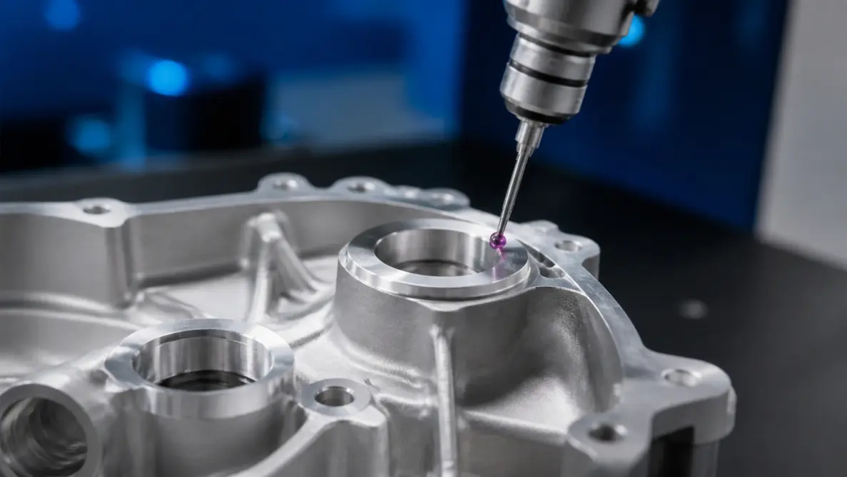
A die casting tolerance is the most the finished part can drift from the size you drew. It's usually written with a plus and minus value. For example: 25.00 mm ±0.10 mm.
Tolerances cover length, location, flatness, angle, and where a surface sits relative to a reference (called a datum). They exist because no process is perfect. Metal shrinks as it cools. Dies flex under injection pressure. Slides shift a tiny bit every shot.
The tolerance you specify is your way of telling the manufacturer how much of that natural drift is okay. Tighter spec, tighter control, higher cost.
Specifying tolerances well is one of the highest-leverage moves a designer can make. Last quarter, our team reviewed a customer drawing that called for Precision tolerance on 47 features. After our DFM review, only 6 actually needed it. We re-quoted the program at roughly 18% less without changing the function of a single part. We see this pattern on most die casting quotes that land on our desk.
What Are NADCA Tolerance Standards?
The NADCA Product Specification Standards for Die Castings is the reference manual used across North America. It splits die casting tolerances into two tiers: Standard and Precision. The part you're making doesn't change. What changes is the level of care during tooling, casting, and inspection.
What Are NADCA Standard Tolerances?
Standard tolerances are what a well-run die casting shop holds in normal production. Normal die life. Normal inspection. Normal tooling maintenance.
For a linear dimension up to one inch, NADCA Standard is roughly ±0.010" (±0.25 mm). Add ±0.001" for each extra inch of length. This is the default you should design to unless a feature has a real reason to be tighter.
What Are NADCA Precision Tolerances?
Precision tolerances are what a die casting shop can hold when it pays extra attention. That means tighter tooling, more frequent die service, in-process measurement, and higher scrap.
For the same one-inch linear dimension, NADCA Precision is around ±0.002" (±0.05 mm). Add ±0.001" for each extra inch. Precision die casting tolerances are best reserved for mating features, bearing seats, sealing surfaces, and locating datums.
Quick Rule of Thumb: What Each Tier Costs You
Standard tolerances are basically free. Precision tolerances usually add 10 to 25 percent to the part price. The extra cost comes from higher scrap, more inspection time, and faster tool wear.
Tighter than Precision (often called "as-machined") means a secondary CNC operation. That adds even more cost but unlocks tolerances down to ±0.01 mm.
How Do NADCA Tolerances Compare to ISO 8062?
Outside North America, the dominant standard is ISO 8062. It uses CT (Casting Tolerance) grades from CT1 (tightest) to CT16 (loosest).
According to Engineers Edge, normal high-pressure die casting falls around CT5 to CT7 for aluminum and magnesium, CT4 to CT6 for zinc, and CT6 to CT8 for copper.
If your supply chain runs across multiple regions, put both NADCA and ISO grades on the drawing. It saves a lot of email back and forth at quote time.
What Is the Die Casting Tolerance Chart by Feature Type?
Different features get different tolerance treatments because they're formed by different parts of the tool. Here's the snippet-friendly version first, then the detailed chart.
| Feature | Standard | Precision |
|---|---|---|
| Linear (first inch) | ±0.010" | ±0.002" |
| Flatness (first 3 inches) | 0.012" | 0.005" |
| Draft, inside walls | 1° to 2° | 0.5° to 1° |
| Draft, outside walls | 0.5° to 1° | 0.25° to 0.5° |
| Cored hole draft | 2° per side | 1° per side |
And here's the fuller chart that includes the extra tolerances added for parting line and slide features.
| Feature Type | NADCA Standard | NADCA Precision | Notes |
|---|---|---|---|
| Linear (within one die half), first inch | ±0.010" / ±0.25 mm | ±0.002" / ±0.05 mm | Add ±0.001" per extra inch |
| Across parting line (added to linear) | +0.012" typical | +0.005" typical | Look up by projected area in NADCA Section 4A |
| Moving die slide (added to linear) | +0.012" typical | +0.006" typical | Look up by slide projected area in NADCA Section 4A |
| Parting line shift (added to linear) | ±0.008" typical | ±0.004" typical | Look up by projected area in NADCA Section 4A |
| Flatness (first 3 inches) | 0.012" | 0.005" | Add 0.004" Standard or 0.002" Precision per extra inch |
| Draft angle, inside walls | 1° to 2° | 0.5° to 1° | Inside walls need twice the draft of outside walls |
| Draft angle, outside walls | 0.5° to 1° | 0.25° to 0.5° | Going below Precision risks galling and tool damage |
| Cored hole draft | 2° per side | 1° per side | Shrinkage onto cores needs extra draft |
Values above are summarized from NADCA's published tolerance tables. The added tolerances for parting line, slide, and shift features change with the projected area of the casting. Always look up the exact value in the NADCA specification for your part.
What Is Linear Tolerance in Die Casting?
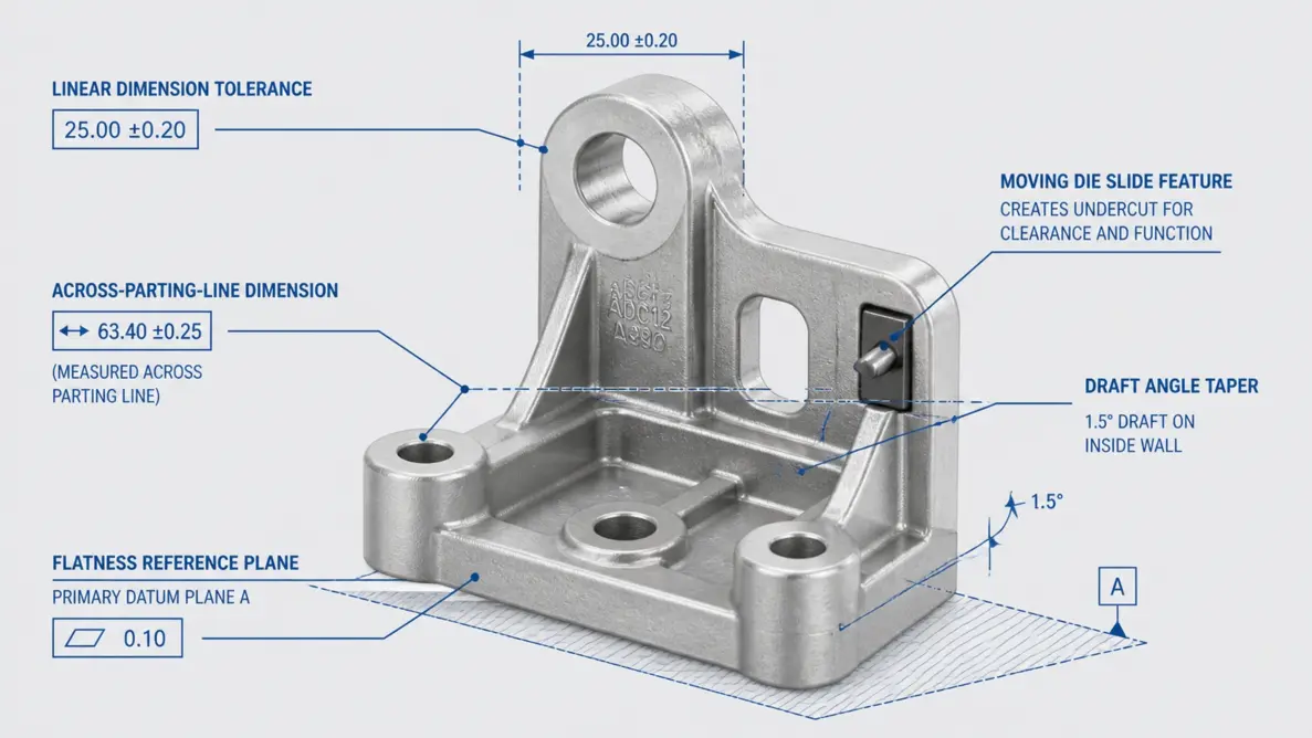
Linear tolerance is the allowed drift on a straight-line dimension that lives inside one half of the die. Both ends of the dimension are formed by the same piece of steel. That's why it's the tightest tolerance the casting process can hold without machining.
The math is simple. Take the NADCA base value for the first inch. Add the per-inch adder for every extra inch.
Example: a 5-inch linear feature held to Precision. Base is ±0.002". Add four times ±0.001" for the extra inches. Total is ±0.006".
This is the dimension type that gives you the most room to work with. If you can route a tight dimension between two features in the same die half, do it. You'll save real money.
What Is Parting Line Tolerance and Parting Line Shift?
Parting line tolerance kicks in any time a dimension crosses from one die half into the other. Two things happen at the parting line, and you have to plan for both.
The first is die separation. Molten metal pressure pushes the two die halves apart by a tiny amount. This only adds material to the part, so NADCA only adds extra tolerance to the high side. A 5" feature across the parting line might carry a Precision tolerance of -0.006" / +0.011" instead of an even ±0.006".
The second is parting line shift. This is a side-to-side misalignment between the two die halves. It comes from guide pin wear, heat differences, or wear on the casting machine. The shift tolerance is added evenly to both sides of the linear tolerance.
The total parting line tolerance on a feature is the sum of three things: linear tolerance, across-parting-line tolerance, and parting line shift tolerance.
How Are Tolerances on Moving Die Slides Handled?
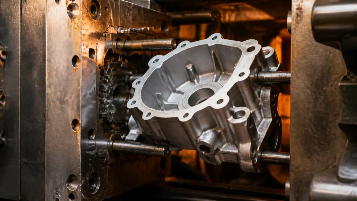
Slides are the moving steel inserts that form undercuts, side holes, and external features that can't release with a straight-pull die.
Slides physically move. They're held in place by hydraulic or mechanical clamps, but they still shift a small amount under injection pressure. That shift gets added to the linear tolerance for any feature the slide forms.
The extra slide tolerance grows with the projected area of the slide face hit by the molten metal. A small 1-inch diameter core barely moves. A large flat slide can shift several thousandths of an inch under full shot pressure.
Rule of thumb: slide features are always looser than fixed die features. If a tight dimension lives on a slide, you have two options. Either machine it after casting. Or redesign the part so the feature can be formed by a fixed die half.
How Are Flatness and Angularity Controlled?
Flatness measures how much a surface deviates from a perfect plane. The NADCA Precision tolerance for flatness is 0.005" for the first 3 inches and 0.002" for each extra inch, per the General Die Casters dimensional capability guide. An 8-inch flat surface, for example, would have a Precision flatness of about 0.015".
Angularity is a group of tolerances that includes parallelism, perpendicularity, and the angle between two surfaces. NADCA's Precision angularity is about 0.003" for the first inch and 0.001" for each extra inch. Features inside one die half hold tighter angularity than features that cross the parting line.
Here's something most design guides miss. Flatness and angularity are driven as much by part design as by process control. A thin, unsupported flange will warp. A ribbed, well-supported one won't. If you need a flat surface on a casting, add ribs and bosses around it so the part stiffens itself as it cools.
What Is a Typical Die Casting Draft Angle?
A die casting draft angle is the slight taper added to vertical walls so the part can pop out of the die without sticking.
Without draft, the casting would weld itself to the steel as it shrinks. That tears the part surface or damages the die. Either way, you lose money.
Standard NADCA guidance, which we follow on most projects:
- Outside walls: 0.5° to 1° of draft
- Inside walls: 1° to 2° (twice as much as outside walls, because the casting shrinks onto inside features as it cools)
- Cored holes: 2° per side
- Textured surfaces: add 1° per 0.1 mm of texture depth
According to Xometry's die casting design guide, a useful rule of thumb is to add 1° of draft for every 25 mm of cavity depth. Going below the minimum draft on short walls is technically possible. It also shortens die life and risks galling (where the part scrapes metal off the die during ejection).
How Do Die Casting Tolerances Differ by Alloy?
Not all die cast alloys hold the same tolerances. Zinc is the tightest. Aluminum is the workhorse middle ground. Magnesium sits in between.
The differences come from melt temperature, shrinkage rate, and how the alloy fills thin sections. Aluminum has higher shrink, so it drifts more during cooling. Zinc has low shrink and a low melt temperature, so it holds tiny features cleanly. For alloy choices that sit outside high-pressure die casting (like A356 in gravity casting or A356 in sand casting), the tolerance ranges open up further because the process pressure is lower.
| Alloy Family | Tightest As-Cast Linear Tolerance | Common Uses | Why It Holds (or Doesn't) |
|---|---|---|---|
| Zinc (Zamak 3, 5, 7) | ±0.001" to ±0.002" / ±0.025 to ±0.05 mm | Small precision hardware, electrical connectors, decorative parts | Low melt temperature (about 385°C), low shrink, easy on the die |
| Aluminum (A380, ADC12, A360) | ±0.002" to ±0.004" / ±0.05 to ±0.10 mm | Housings, brackets, automotive structural parts, heat sinks | Higher melt, more shrink, slightly looser tolerances |
| Magnesium (AZ91D, AM50) | ±0.002" to ±0.003" / ±0.05 to ±0.08 mm | Lightweight structural parts, automotive interior, portable electronics | Great castability and low density, but reactive in process |
These ranges line up with practical guidance from Dynacast's precision die casting FAQ. Our own zinc capacity runs from 25 to 168 tons (parts from 1 g to about 1,500 g). Aluminum runs from 180 to 800 tons (parts from 1 g to about 5,000 g). Both build to ASTM B85. Magnesium follows aluminum tooling practice with stricter atmosphere control.
Should I Hold a Feature As-Cast or Machine It?
Once you cross from Precision tolerance into "tighter than Precision," you've left the casting process. You're now describing a part that needs custom CNC machining as a secondary operation. The choice of as-cast vs. machined is one of the biggest cost drivers on any die casting program.
| Situation | Hold As-Cast | Add Machining |
|---|---|---|
| Feature is non-functional or cosmetic only | Yes | No |
| Required tolerance is wider than ±0.05 mm | Yes | No |
| Feature is a mating face, bearing seat, or O-ring groove | No | Yes |
| Required tolerance is tighter than ±0.05 mm | No | Yes |
| Feature lives on a slide | Maybe (only if loose tolerance) | Often yes |
| Surface roughness must be Ra 1.6 μm or finer | No | Yes |
Here's our take, and it goes against what some design guides say. You don't need to machine every important-looking feature. Most of the time, a Precision-toleranced as-cast feature performs just as well as a machined one at a fraction of the cost.
The right move is to flag the features that truly need tight control, machine those, and let everything else come off the die as-is. That single decision usually saves more money than any other DFM call on a die casting program.
What Is Tolerance Stack-Up in Die Cast Assemblies?
Tolerance stack-up is the running total of individual feature tolerances across a finished assembly. When you bolt two die castings together, every individual tolerance adds to the final fit. Same when you bolt a casting to a stamping, or a casting to a machined housing.
There are two ways to calculate stack-up. Each tells a different story.
Worst-case analysis adds every tolerance together. It assumes every part is at its extreme limit at the same time. It's safe, but it can drive cost through the roof.
Root Sum Square (RSS) analysis is statistical. It takes the square root of the sum of squared tolerances. It predicts the drift that roughly 99.7 percent of assemblies (3-sigma) will fall within.
Quick example. Five features each at ±0.1 mm. Worst-case stack: ±0.5 mm. RSS stack: only ±0.22 mm.
For most production die casting programs, we recommend RSS. It reflects how parts actually behave in volume. It also keeps you from over-tolerancing features that don't need it.
How Do You Decide What Tolerance to Specify? The TIGHT Framework
After years of reviewing customer drawings, our team built a short mental checklist for deciding what tolerance a feature actually needs. We call it TIGHT. Run every dimension through these five questions before you lock the drawing.
The TIGHT Framework
T — Tolerance: What's the loosest tolerance that still lets the feature do its job? Start there, not at ±0.05 mm.
I — Importance: Is this feature truly functional? Or is it cosmetic, clearance, or a holdover from a CAD template?
G — Geometry: Is the feature inside one die half, across the parting line, or on a slide? Each one gets a different tolerance budget.
H — Handling tweaks: Can you redesign so the feature lives inside one die half? Or so the load path doesn't depend on a tight tolerance?
T — Tradeoff cost: Is the saving from a looser spec worth more than the assembly cost of a tighter one? In most cases, yes.
If a feature passes all five checks, specify Precision. If it fails one or two, default to Standard. If it fails three or more, you probably have a design problem, not a tolerance problem.
How Should You Specify Die Casting Tolerances on a Drawing?
Most drawing problems we see at quote time come from one of three places. Tolerances applied without thinking. Datums chosen across the parting line. Or a generic title block tolerance that quietly forces every dimension into Precision territory.
Here's a short rule list that prevents most of them.
- Use a default title block tolerance of Standard NADCA. Then call out tighter tolerances only on the features that need them.
- Place datums inside one die half. Never put your primary datum on a feature that crosses the parting line or sits on a slide.
- Use GD&T (geometric dimensioning and tolerancing) per ASME Y14.5. Bilateral plus-minus tolerances on casting features usually over-specify.
- Flag machined features explicitly. Mark every feature that needs secondary CNC with a "Machined" callout so there's no ambiguity at the quote stage.
- List both NADCA Standard/Precision and ISO 8062 CT grade if your supply chain spans North America and Asia.
- Ask for a DFM review before releasing the drawing. A 30-minute review with your caster catches more problems than three rounds of revisions later.
For complex programs, our R&D engineering team marks up your drawing during the quote and suggests which features to open up, tighten, or move to a secondary operation. DFM feedback comes with every quote we send.
What Separates a Good Die Caster From a Mediocre One?
Three things, in our experience.
First is the willingness to push back on a drawing. Most shops just quote what's drawn. The good ones look at the tolerance callouts, flag the ones that don't need to be that tight, and tell you. That single habit saves customers more money than any process upgrade.
Second is process discipline backed by data. NADCA tolerances aren't a guarantee. They're a target. A shop that can actually hit them in volume has a real quality system behind it, with documented APQP, PPAP, SPC, and PFMEA. Look for IATF 16949:2016 certification, which builds on ISO 9001:2015 and adds automotive-grade controls.
Third is the ability to handle the next step in-house. If your part needs CNC machining after casting (and most precision die castings do), running both stages under one roof eliminates the handoff variation between separate vendors. That's where most quality and lead time wins actually happen.
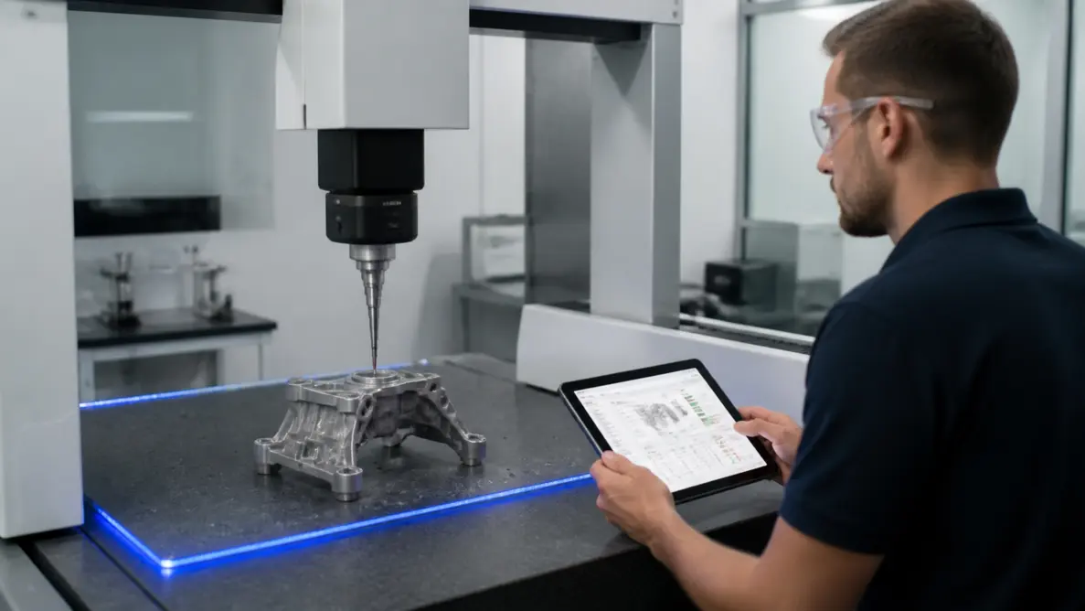
Meco runs die casting services across 36,000 square meters of facility space in Thailand and China, with U.S. engineering support. We're IATF 16949:2016 certified. Capacity covers zinc from 25 to 168 tons and aluminum from 180 to 800 tons, both per ASTM B85. Every program ships with FAI, optional PPAP, CMM reports at ±0.002 mm resolution, and full lot traceability. For multi-stage programs that combine casting, machining, and finishing, our turnkey manufacturing model puts every step under one accountable partner.
Frequently Asked Questions About Die Casting Tolerances
What are the standard tolerances for die casting?
NADCA Standard linear tolerance is about ±0.010" (±0.25 mm) on the first inch of length, plus ±0.001" for each extra inch. Standard tolerances are what a well-run die casting shop holds in normal production, with normal die life and normal inspection. They are the most cost-effective default and should be used for any feature that doesn't have a specific reason to be tighter.
What is the tightest tolerance you can hold in die casting?
In zinc die casting, the tightest as-cast tolerance is generally between ±0.001" and ±0.002" on small features. Aluminum holds between ±0.002" and ±0.004", and magnesium falls between the two. Tighter than that needs a secondary CNC machining step, which can take dimensions down to ±0.01 mm. The achievable tolerance is also driven by part geometry, projected area, and where on the die the feature sits.
What is the difference between NADCA standard and precision tolerances?
Standard tolerances are what a die casting shop holds using normal manufacturing practice and inspection. Precision tolerances are about five times tighter on linear features and need more careful tooling, more frequent die service, and higher inspection frequency. Precision usually adds 10 to 25 percent to the part price and shortens die life, so it should be reserved for features that truly need tight control.
What is a typical draft angle for die casting?
Typical die casting draft angles are 0.5° to 1° on outside walls and 1° to 2° on inside walls, with cored holes at about 2° per side. Inside walls need twice the draft of outside walls because the casting shrinks onto inside features as it cools. A useful rule of thumb is to add 1° of draft for every 25 mm of cavity depth, plus extra draft for textured surfaces.
What is parting line tolerance in die casting?
Parting line tolerance is the extra tolerance applied to any dimension that crosses from one die half into the other. It covers two effects: die separation under injection pressure (which only adds material to the part) and parting line shift from wear or thermal differences (which can move the dies in either direction). The extra tolerance scales with the projected area of the casting and is added to the base linear tolerance.
How tight a tolerance can aluminum die casting hold?
Aluminum die casting typically holds linear tolerances between ±0.002" and ±0.004" (±0.05 to ±0.10 mm) on small features. The exact tolerance depends on alloy (A380, ADC12, A360), part geometry, projected area, and whether the feature lies inside one die half, across the parting line, or on a slide. Tighter aluminum tolerances are achievable with a secondary CNC machining step.
How tight a tolerance can zinc die casting hold?
Zinc die casting holds the tightest as-cast tolerances of any common die cast alloy. Typical tightest values are ±0.001" to ±0.002" (±0.025 to ±0.05 mm) on small features. Zinc's low melt temperature and low shrinkage make it ideal for small precision parts like electrical connectors, hardware, and decorative components that need fine detail without secondary machining.
Why does die casting need a draft angle?
Die casting needs a draft angle so the part can be ejected cleanly from the die without sticking. As molten metal solidifies, it shrinks and grips the die surfaces. Without draft (the slight taper on vertical walls), ejection would tear the surface of the part and damage the die. Inside walls need more draft than outside walls because the casting shrinks onto inside features as it cools.
What is tolerance stack-up in die casting?
Tolerance stack-up is the running total of individual feature tolerances across a finished assembly. Worst-case analysis adds every tolerance arithmetically. Root Sum Square (RSS) analysis is statistical and predicts the drift that 99.7 percent of assemblies will fall within. Five features each at ±0.1 mm produce a worst-case stack of ±0.5 mm but an RSS stack of only ±0.22 mm.
Should I machine a feature or hold it as-cast?
Hold a feature as-cast whenever the required tolerance is wider than about ±0.05 mm and the feature is non-mating or cosmetic. Add CNC machining when the feature is a mating face, bearing seat, sealing surface, or has a tolerance tighter than ±0.05 mm. Features that live on a slide are also strong candidates for machining because slide tolerances are looser than fixed die features. Running die casting and CNC under one roof eliminates the handoff variation between separate vendors.
Get Die Cast Parts That Hit Your Tolerances the First Time
Specifying the wrong tolerance on a die cast feature is one of the most expensive mistakes in manufacturing. Specifying the right one, with DFM feedback before you release the drawing, saves cost, shortens lead times, and protects die life.
With 30+ years of turnkey manufacturing experience and IATF 16949:2016 certified quality, Meco runs die casting and downstream CNC machining under one roof. You get one accountable partner from raw alloy to finished part.
- Full Alloy Range: Zinc (Zamak 2, 3, 5, 27) from 25 to 168 tons; aluminum (ADC12, A360, A380, AlSi10Mg, AlSi12) from 180 to 800 tons; magnesium (AZ91D, AM50, AS41). All per ASTM B85.
- NADCA Tolerances Built In: Standard ±0.010" basic to 1", Precision to ±0.002". Tighter via CNC to ±0.01 mm.
- IATF 16949:2016 Certified: Automotive-grade quality across every industry. 99.99% quality rate. 99.8% on-time delivery.
- DFM Tolerance Review with Every Quote: Engineering review on every drawing, returned in under 24 hours.
- 40+ In-House Processes: Die casting, CNC machining, surface finishing, assembly, and global logistics under one roof.
Upload your CAD files and let our engineering team flag the features that should be tightened, opened up, or moved to a secondary operation before tooling starts.
Request a Quote Today