
Surface Finish Symbols Explained: How to Read a Callout
Surface finish symbols are the small checkmark-shaped marks on an engineering drawing that tell the shop how rough or smooth a surface must be. The basic symbol is a checkmark resting on the surface line, and numbers and marks around it spell out the roughness value, the direction of the tool marks, and whether the surface must be machined. Once you know where each piece sits, any callout is easy to read.
This guide shows you the symbol position by position, explains lay direction, and compares the two standards that govern these marks: ASME Y14.36 in North America and ISO 1302 internationally. Every detail here matches ASME Y14.36 and ISO 21920, the current standard behind ISO 1302 symbols.
What Do Surface Finish Symbols Mean?
Surface finish symbols, also called surface texture symbols, are a standard way to put roughness requirements on a drawing. Instead of writing a sentence, an engineer draws one small mark that the whole world can read the same way. They control how the surface is made and inspected.
The symbol does three main jobs: it states the roughness value (usually Ra), it can require or forbid machining, and it can add detail like lay direction or a second roughness parameter. The more positions that are filled in, the more control the engineer is asking for.
What Does the Checkmark Symbol Mean?
The checkmark is the base surface finish symbol. Its point rests on the surface line it controls. On its own, the plain checkmark means the surface needs a finish but lets the shop decide how to make it.
Two common variations change that. A bar across the top means the surface must be machined (material has to be removed). A small circle in the corner means the opposite: do not machine, leave it as cast, forged, or molded.
How to Read a Surface Finish Symbol: Position by Position
Every surface finish symbol has set positions around the checkmark, and each position holds one piece of information. Learn the positions once and you can read any callout. The table below breaks down what goes where.
| Position | What It Shows | Example |
|---|---|---|
| a | Roughness value, usually Ra | 3.2 or 125 |
| Bar on top | Machining is required | Material must be removed |
| Circle at base | No machining allowed | Leave as cast or forged |
| b | Production method or note | GRIND, HONE |
| c | Sampling length | 0.8 mm |
| d | Lay direction | Parallel, perpendicular, circular |
| e | Minimum material removal | 2 mm |
| f | Second roughness parameter | Rz value |
The Ra Value (Position a)
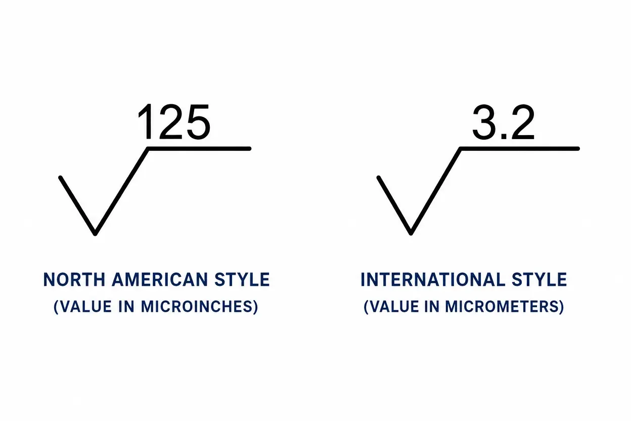
Position a holds the number engineers care about most: the Ra roughness value. It sits just above the checkmark point. On North American drawings it is in microinches, like 125. On metric drawings it is in micrometers, like 3.2. For what each value means in use, see our guide to surface finish Ra values.
The Machining-Required Bar
A bar across the top of the checkmark means the surface must be machined. This is a firm instruction, not a suggestion. Missing this bar on a cast or forged part is a common and costly error, because the shop may ship a rough face that was supposed to be machined smooth.
The No-Machining Circle
A small circle where the checkmark meets the surface line means do not machine. The surface must stay as produced by casting, forging, or molding. Engineers use it to protect a finish that is already correct and to avoid paying for needless machining.
What Is Lay Direction in Surface Finish?
Lay direction is the direction of the dominant pattern of tool marks on a surface. Picture the grain on a piece of wood. Lay matters because it affects how parts slide, seal, and wear, so some drawings control it with a symbol in position d.
For example, a shaft that spins inside a seal may need the lay running around the part, not along it, so the seal rides smoothly. The table below lists the standard surface finish lay direction symbols and what each one means.
| Lay Symbol | Meaning | Common Process |
|---|---|---|
| = | Lay parallel to the edge shown | Shaping, planing |
| Perpendicular | Lay at a right angle to the edge | Turning across, facing |
| X | Lay crosses in two directions | Honing |
| M | Lay is multidirectional, no pattern | Lapping, blasting |
| C | Lay is circular around the center | Facing on a lathe |
| R | Lay is radial from the center | Some grinding |
| P | Lay is particulate, non-directional | Bead blasting |
When Lay Matters Most
Most drawings leave lay direction out, and that is fine for parts that just bolt together. Specify it only when the part seals or slides, like shaft seals, hydraulic bores, and gasket faces. Adding a lay callout to a part that does not need it can raise cost for no benefit.
Surface Finish Standards: ASME Y14.36 vs ISO 1302
Two standards control how surface finish symbols are drawn, and knowing which one your drawing follows tells you how to read it. ASME Y14.36 is the North American standard, and ISO 1302 is the international one used across Europe and Asia. They share the same checkmark idea but differ in details.
| Feature | ASME Y14.36 | ISO 1302 |
|---|---|---|
| Region | North America | Europe, Asia, global |
| Default unit | Microinch (µin) | Micrometer (µm) |
| Current edition | ASME Y14.36-2018 | Parameters now per ISO 21920 (2021) |
| Symbol style | Checkmark, positions a to f | Checkmark, similar layout |
| Common value | 125 µin standard machined | 3.2 µm standard machined |
What Is ASME Y14.36?
ASME Y14.36 is the North American surface texture symbol standard. The current version, ASME Y14.36-2018, replaced the older Y14.36M from 1996. If your parts ship to or from the U.S. or Canada, this is the standard your drawings should follow, and values are usually in microinches.
What Is ISO 1302?
ISO 1302 is the international standard for showing surface texture on drawings, widely used in Europe and Asia. The roughness parameters behind the symbols are now defined by ISO 21920, which replaced the older ISO 4287 and ISO 4288 in 2021. ISO drawings usually call out values in micrometers.
How to Read Any Callout in Order
When a symbol looks busy, read it in the same order every time and it stops being confusing. Our engineers use this simple four-step pass on every drawing.
- Check the base: Plain checkmark, bar (must machine), or circle (do not machine)?
- Read the value: Find the Ra number and confirm the unit, microinch or micrometer.
- Look for lay: Is a lay symbol present? If so, the surface direction is controlled.
- Scan for extras: Note any process note, sampling length, or second parameter like Rz.
Run those four steps and you will never miss the part of a callout that drives cost or function. To match a value across units, use our surface finish conversion chart.
Common Surface Finish Symbol Mistakes
The most expensive symbol errors are simple ones. They usually come from missing the base mark or the unit, not from the fancy positions.
Here is a real example. A customer sent us a cast bracket drawing where one mounting face had a checkmark with a machining bar, but the bar was faint and easy to miss. Read without the bar, the face would have shipped as cast and rough, and it would not have sealed against its mating part.
The Two Mistakes We Catch Most
First, missing the machining bar, so a surface that should be machined ships rough. Second, misreading the unit, so a 125 microinch finish gets treated as 125 micrometers, which is 39 times rougher. Both are caught in our DFM review before any metal is cut.
Our engineering team flagged the faint bar during the DFM review, confirmed the intent with the customer, and machined the face to the right Ra. The part passed first-article inspection on a calibrated profilometer. That kind of check is built into our CNC machining quotes and our surface finishing services. For the full roughness reference, see our surface finish chart, and to see how finish affects total price, read our guide on how much it costs to get a metal part made.
Frequently Asked Questions About Surface Finish Symbols
What do surface finish symbols mean?
Surface finish symbols are standard marks on an engineering drawing that state how rough or smooth a surface must be. The base symbol is a checkmark resting on the surface, with numbers and marks around it for the roughness value, lay direction, and whether machining is required. They let everyone read the same requirement the same way. The most common value shown is the Ra roughness average.
How do you read a surface finish symbol on a drawing?
Start with the base mark to see if the surface must be machined (a bar across the top), must stay unmachined (a circle at the base), or is open (a plain checkmark). Then read the Ra value just above the point and confirm the unit, microinch or micrometer. Finally, check for a lay symbol and any extra notes like a process or a second parameter. Reading it in this order makes any callout clear.
What does the checkmark symbol mean on an engineering drawing?
The checkmark is the basic surface finish symbol, with its point resting on the surface it controls. On its own it means the surface needs a finish but lets the shop choose the method. A bar across the top means the surface must be machined, and a circle at the base means it must not be machined and should stay as cast, forged, or molded.
What is the difference between ASME Y14.36 and ISO 1302?
ASME Y14.36 is the North American surface texture symbol standard and usually calls out values in microinches, while ISO 1302 is the international standard used in Europe and Asia and uses micrometers. Both share the same checkmark layout but differ in default unit and some symbol details. The current ASME edition is Y14.36-2018, and the roughness parameters behind ISO 1302 are now defined by ISO 21920 from 2021.
What does the circle on a surface finish symbol mean?
A small circle where the checkmark meets the surface line means the surface must not be machined. It should stay exactly as produced by casting, forging, or molding. Engineers use it to protect a finish that is already correct and to avoid paying for machining that is not needed. It is the opposite of the bar, which requires machining.
What is lay direction in surface finish?
Lay direction is the direction of the dominant pattern of tool marks on a surface, like the grain on wood. It is shown by a symbol in position d of the surface finish callout. Lay matters for parts that seal or slide, such as shaft seals and hydraulic bores, because the direction of the marks affects how the surfaces ride against each other. Most simple parts do not need a lay callout.
What are the lay direction symbols?
The standard lay symbols are: equals (parallel to the edge), perpendicular (at a right angle), X (crossed in two directions), M (multidirectional), C (circular around the center), R (radial from the center), and P (particulate or non-directional). Each links to a typical process, such as C for facing on a lathe or P for bead blasting. They appear in position d of the surface finish symbol.
What is the standard for surface finish symbols?
Two standards govern surface finish symbols. ASME Y14.36, currently the 2018 edition, is the North American standard and defines the symbol layout and positions. ISO 1302 is the international equivalent used in Europe and Asia, with its roughness parameters now set by ISO 21920 from 2021. Your drawing should follow the standard used in your supply chain and state it clearly.
Where does the Ra value go on a surface finish symbol?
The Ra roughness value goes in position a, just above the point of the checkmark. It is the number engineers care about most, written in microinches on North American drawings or micrometers on metric drawings. For example, a 125 sits in this position on an ASME drawing for a standard machined finish. Other positions hold the lay, sampling length, process note, and any second parameter.
What does a bar across the top of the surface finish symbol mean?
A bar across the top of the checkmark means the surface must be machined, so material has to be removed to reach the finish. It is a firm instruction, not optional. Missing this bar on a cast or forged part is a common and costly mistake, because a rough face that should have been machined may ship as is. Always check for the bar before producing the part.
Get Your Drawings Read Right the First Time
A misread surface finish symbol can ship a rough face that should have been machined, or add cost for a finish you never needed. Meco reviews every callout during DFM and verifies the result on calibrated profilometers, so your parts match the drawing exactly.
With 30+ years of turnkey manufacturing experience and IATF 16949:2016 certified quality, Meco interprets and builds to spec the first time, from prototype through mass production.
- 40+ In-House Processes: CNC machining, surface finishing, casting, grinding, heat treatment, and assembly under one roof.
- IATF 16949:2016 Certified: Automotive-grade quality across every industry. 99.99% quality rate. 99.8% on-time delivery.
- DFM Feedback with Every Quote: We flag missing machining bars and misread units before production, typically saving 15 to 30 percent. Quotes in under 24 hours.
- Profilometer-Verified Finishes: Calibrated Ra measurement with full FAI and CoA documentation.
- Prototype to Mass Production: From 10 pieces to 10 million-plus. No minimum order quantities.
Send us your drawings and let Meco's engineering team confirm every surface finish callout before production starts.
Request a Quote Today