
Medical device prototyping turns a design into testable parts before production. A successful transfer also needs controlled drawings, suitable materials, defined finishing and evidence that the manufacturing process meets the agreed requirements.
CNC machining is useful for functional samples made from specified stock materials. It is one option alongside additive manufacturing and molding. Choose the process for the test objective and intended production route.
A prototype can look correct and still be difficult to manufacture consistently. Fit, surface condition, material identity and inspection methods need attention before a design moves into a production order.
The goal is to learn what each build can prove. An early model may answer a handling question. A later sample may support dimensional verification or a device-level test. These builds need different levels of control.
This guide covers prototype stages, CNC turning, small features, materials, design transfer, quality records and finishing. It also explains what to agree with a supplier before increasing volume.
The broader medical CNC machining guide covers process selection and partner assessment. For this article, the focus is how to carry a component design from an early sample into controlled production.
Key takeaways
- Define the test. Match the prototype's material, geometry and finish to the question being answered.
- Plan the production route. CNC, additive manufacturing and molding can each have a role.
- Control small features. Burrs, workholding and measurement access can matter as much as nominal size.
- Document each build. Link samples to drawing revisions, material lots and inspection results.
- Assess changes. Using the same supplier does not remove the need to review process changes.
- Agree the evidence package. Inspection and validation needs depend on the component and device program.
What Is Medical Device Prototyping?
Medical device prototyping creates physical models or components for design learning and testing. A prototype's value depends on how well it represents the characteristics that matter to that test.
For example, an enclosure model may help check handling and assembly access. A machined shaft may be used to examine fit and movement. A material-sensitive test needs a sample chosen for that specific purpose.
Separate appearance from test evidence
A visual model is useful, but it does not establish strength, cleaning performance or biological safety. Record the purpose of each build so a sample is not later used to support a claim it cannot justify.
- Form. Check size, shape and handling.
- Fit. Check interfaces, clearances and assembly.
- Function. Test the intended movement or performance.
- Manufacturability. Check tool access, workholding and inspection.
Define the expected result before making the part. A drawing alone may not explain the test fixture, mating components or operating conditions. Share those details when they affect the sample.
How Does Medical Prototyping Differ from General Prototyping?
Medical programs place particular emphasis on sample suitability, traceable records and the consequences of design changes. The required controls depend on intended use, development stage and the applicable quality and regulatory framework.
Material and process representation
A substitute material may be suitable for checking grip or packaging. It may be unsuitable for a test affected by stiffness, wear, heat or surface condition. Agree which differences are acceptable before interpreting the results.
A change from machined stock to printed material, or from machining to molding, can change relevant properties. Review the impact rather than assuming that matching CAD geometry makes the parts equivalent.
Build records and revision control
Record the drawing revision, material identity, sample quantity and any deviations. Later testing should be traceable to the actual configuration supplied. A measurement report loses value when the team cannot identify which design it represents.
Regulatory context in 2026
The FDA's Quality Management System Regulation took effect on 2 February, 2026. It incorporates ISO 13485:2016 by reference within 21 CFR Part 820. Applicability depends on the manufacturer's role and device.
Meco's confirmed certification is IATF 16949:2016. It is not evidence of ISO 13485 certification or device approval. Agree supplier responsibilities and required records with the device manufacturer's quality team before starting the program.
What Are the Stages of Medical Device Prototyping?
Teams often use proof-of-concept, alpha, beta and pilot builds to organize development. These labels are planning conventions, not a universal regulatory sequence. Define the entry criteria and approval decision for each stage.
| Stage | Main question | Manufacturing focus | Useful records |
|---|---|---|---|
| Proof of concept | Does the principle work? | Simple models or selected functional features | Test purpose, observations and limitations |
| Alpha | Do the parts fit and function? | Closer geometry and relevant materials | Revision, inspection and design review |
| Beta | Does the design meet defined requirements? | Samples appropriate to the planned tests | Build configuration and test evidence |
| Pilot | Can the planned process repeat the result? | Production routing, fixtures and controls | Inspection, capability and validation evidence as required |
| Production | Can output remain controlled? | Released instructions and change control | Lot records, acceptance results and deviations |
Make each build answer a decision
Do not advance simply because a batch has been delivered. Review its results against the agreed criteria. Identify unresolved issues before approving a new revision or ordering production tooling.
The beta-to-pilot transition often exposes differences between a carefully adjusted sample and a repeatable process. Check assembly variation, tool wear and inspection consistency. A pilot build should exercise the planned controls rather than hide problems through undocumented adjustments.
When Is CNC Machining Suitable for Medical Prototypes?
CNC machining is useful when samples need specified stock materials, accurate interfaces and controlled machined surfaces. It can support functional testing without the lead time of a dedicated mold.
The method must still fit the design and test. Deep internal passages, porous structures or high-volume plastic parts may favor another route. Manufacturing process selection should follow requirements rather than a blanket preference.
| Consideration | CNC machining | Metal additive manufacturing | Polymer printing or molding |
|---|---|---|---|
| Material route | Machining from specified stock | Powder or other feedstock with process-dependent structure | Printed or molded resin with process-dependent properties |
| Useful geometry | Accessible bores, threads and mating faces | Complex shapes and selected internal structures | Concept models or production-intent plastic geometry |
| Surface condition | Tool marks and finishing must be controlled | Supports, roughness and post-processing need review | Layers, gate effects or shrinkage need review |
| Scale-up question | Fixtures, cycle time and tool life | Build consistency and post-processing | Print capacity or molding tool and process control |
The FDA has published technical guidance for additive manufactured medical devices. This is why it is inaccurate to describe 3D printing as inherently limited to nonfunctional models.
Metal 3D printing and plastic 3D printing can support development where suitable. Confirm the material, post-processing and test relevance before selecting either method.
Machined samples before molded parts
Machined plastic components may help test interfaces while injection molding tooling is developed. The later molded part can differ in shrinkage, orientation and surface details.
Document the bridge sample's limitations. Plan the checks needed on molded parts before treating the earlier results as transferable. The plastic injection molding guide explains the underlying process.
What Is Medical CNC Turning?
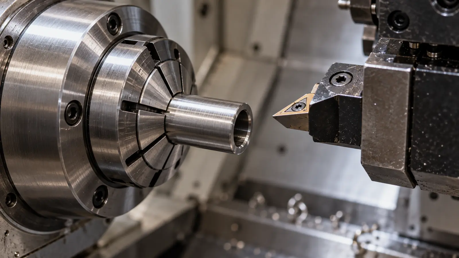
CNC turning rotates the workpiece while cutting tools create features such as diameters, shoulders, grooves and threads. It is useful for cylindrical components used in instruments, equipment and some implant designs.
Swiss-type turning supports slender stock close to the cutting zone. Whether it is the right choice depends on the part's dimensions, material and operations. Do not infer equipment availability or capability from the process name alone.
Features that need attention
- Interfaces. Define the mating diameter, fit and datum relationship.
- Threads. Specify the form, inspection method and edge requirements.
- Long shafts. Review deflection, straightness and handling.
- Thin sections. Check cutting forces, clamping and distortion.
- Edges. Define acceptable burr removal without damaging functional geometry.
Bone screws, dental interfaces, instrument shafts and small tubular parts illustrate the range of turned geometry. Their clinical suitability comes from device-specific design and evidence, not from the turning process itself.
Meco's general CNC reference includes ±0.01 mm machining capability. Treat it as a capability reference, not an automatic tolerance for every surface. Send the drawing for review and confirm how each critical feature will be measured.
What Changes When Medical Components Have Small Features?
Small-feature machining needs close attention to tool behavior, handling and measurement. A miniature bore or thin wall can be difficult to hold and inspect even when its nominal dimensions appear simple.
The term micro machining does not establish one universal feature size or tolerance. Evaluate the complete geometry and proposed process. Unsupported claims about minimum tool diameter or wall thickness should not become purchasing specifications.
| Feature | Manufacturing question | Inspection question |
|---|---|---|
| Small bore | Can the tool reach it and clear chips? | Can size and location be checked reliably? |
| Thin wall | Will clamping or cutting distort it? | Will measurement force distort it? |
| Fine edge | How will burrs be removed? | What is the edge acceptance criterion? |
| Internal passage | How will residue be removed? | Can cleanliness and continuity be assessed? |
Handle the part as part of the process
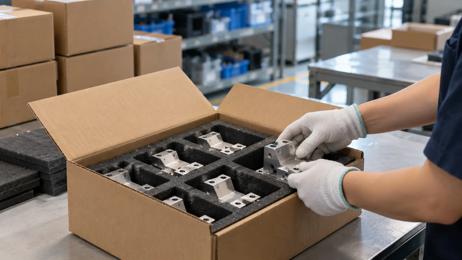
Use fixtures and packaging suited to the geometry. Repeated handling can bend a delicate component or damage a finished edge. Define how parts are transferred between machining, finishing and inspection.
Measurement access should be considered during design review. If a required feature cannot be checked using the proposed method, resolve that issue before production. A precise drawing needs a workable acceptance method.
What Materials Are Used in Medical Device CNC Machining?
Material selection depends on function, loading, patient contact, cleaning and the intended manufacturing route. A familiar material name is not enough. Specify its grade, condition and any required supporting documentation.
| Material family | Possible component context | What to confirm |
|---|---|---|
| Titanium | Selected implant or instrument designs | Specified grade, condition and source records |
| Stainless steel | Instruments, shafts and equipment components | Grade, heat treatment, corrosion and finishing needs |
| Cobalt-chrome alloys | Selected wear-bearing designs | Device specification and supplier capability |
| PEEK | Selected plastic functional components | Exact resin grade and applicable evidence |
| Aluminum | Equipment housings and structural parts | Alloy, temper, finish and intended exposure |
| UHMWPE | Selected polymer bearing designs | Grade, material history and machining behavior |
Biological evaluation is device-specific
The FDA's biocompatibility evaluation framework considers contact type and duration. It is not a universal test checklist. Existing evidence, additional testing or a justified rationale may address the relevant endpoints.
A material certificate confirms specified material information. It does not alone establish the biological safety of a finished device. Include relevant process and surface changes in the device team's evaluation.
Trace the material used in the test
Link each sample to its material lot and agreed certificates. Record any substitution before testing. A result from one grade or condition should not silently become evidence for a different material.
The companion medical plastics machining article covers polymer machining considerations. Confirm specialist grades and documentation during quotation rather than assuming availability.
Share the drawing, test purpose and documentation requirements for a DFM review. Confirm critical features before committing to the next build.
Get DFM Feedback on Your DesignHow Does Design Transfer Work?
Design transfer turns approved design information into usable production instructions and controls. It connects drawings, process routing, inspection and acceptance so production can deliver the intended result.
Build a transfer package
- Design. Release drawings, models, materials and finish requirements.
- Process. Identify programs, fixtures, tools and operation sequence.
- Inspection. Define characteristics, methods, sampling and acceptance.
- Risk. Review potential failures and the controls used to address them.
- Changes. Define who approves revisions and assesses their effect.
A prototype program may include manual adjustments that cannot be repeated reliably. Capture the method or replace it with a controlled operation. The transfer should make the process understandable to production staff beyond the original developer.
Verification and validation have different roles
Design verification checks whether outputs meet specified inputs. Design validation evaluates whether the device meets user needs and intended use. Manufacturing process validation addresses the ability of a process to deliver its intended output.
Not every machining operation requires the same validation approach. The responsible quality team should determine the applicable requirements, including whether results can be adequately verified through inspection and testing.
Where qualification activities are needed, installation, operating-range and production-performance checks may form part of the plan. Define the protocol and acceptance criteria. Do not assume that three batches or one fixed capability index is sufficient for every device.
Supplier continuity helps but does not remove change control
Keeping one supplier can preserve programs, fixtures and process knowledge. It does not eliminate transfer risk. New equipment, material sources, locations or finishing routes may still require review and additional evidence.
Meco's workflow connects quote and DFM feedback, tooling kickoff, sample verification and production launch. Its APQP, PFMEA, control-plan and inspection tools can support the agreed supplier evidence package. They do not replace the device manufacturer's responsibilities.
What Changes When Production Volume Increases?
Scaling requires more than running the prototype program for longer. Tool wear, material variation and repeated setup can affect dimensions and surface condition. Build controls around the actual sources of variation.
| Area | Prototype focus | Production focus |
|---|---|---|
| Fixtures | Support learning and sample geometry | Repeatable location and loading |
| Tool life | Record tools used and observations | Defined monitoring and replacement |
| Inspection | Confirm sample suitability | Control lot acceptance and variation |
| Records | Link results to build revision | Link output to controlled process and lot |
| Changes | Record revisions and deviations | Approve changes and assess their impact |
Use capability data in context
Statistical process control, or SPC, helps monitor variation. Capability indices such as Cpk need appropriate data and a suitable measurement system. A single reported value does not prove every feature or future batch will conform.
Agree the characteristics to study, the sample basis and the response to an out-of-control signal. Keep dimensional acceptance distinct from broader device performance and safety evidence.
Plan timing with the actual scope
Meco lists prototype parts at 1 to 2 weeks as a general planning benchmark. Material sourcing, finishing, documentation and testing can add time. Confirm the quotation's scope and schedule.
A manufacturing lead time is not a regulatory approval timeline. Plan device testing, review and release separately. The R&D engineering team can help review manufacturing steps and open design questions.
What Quality Documentation Should Be Agreed?
Agree documentation before the first sample order. Requirements depend on the component, customer quality system and intended use of the samples. Avoid requesting a generic package without defining what it must prove.
- First article inspection. Link results to drawing characteristics and the supplied revision.
- Measurement reports. Record methods and results for the agreed dimensions and surface requirements.
- Material records. Provide the certificates and lot links specified in the order.
- Process records. Identify relevant routing, programs, controls and deviations.
- Lot traceability. Connect accepted parts to material and manufacturing records.
- Additional evidence. Agree capability, measurement-system studies or testing where needed.
PPAP is an agreed package, not a universal medical requirement
Production Part Approval Process, or PPAP, comes from automotive quality practice. A customer may request it or adapt its elements. It should not be described as mandatory for every medical component.
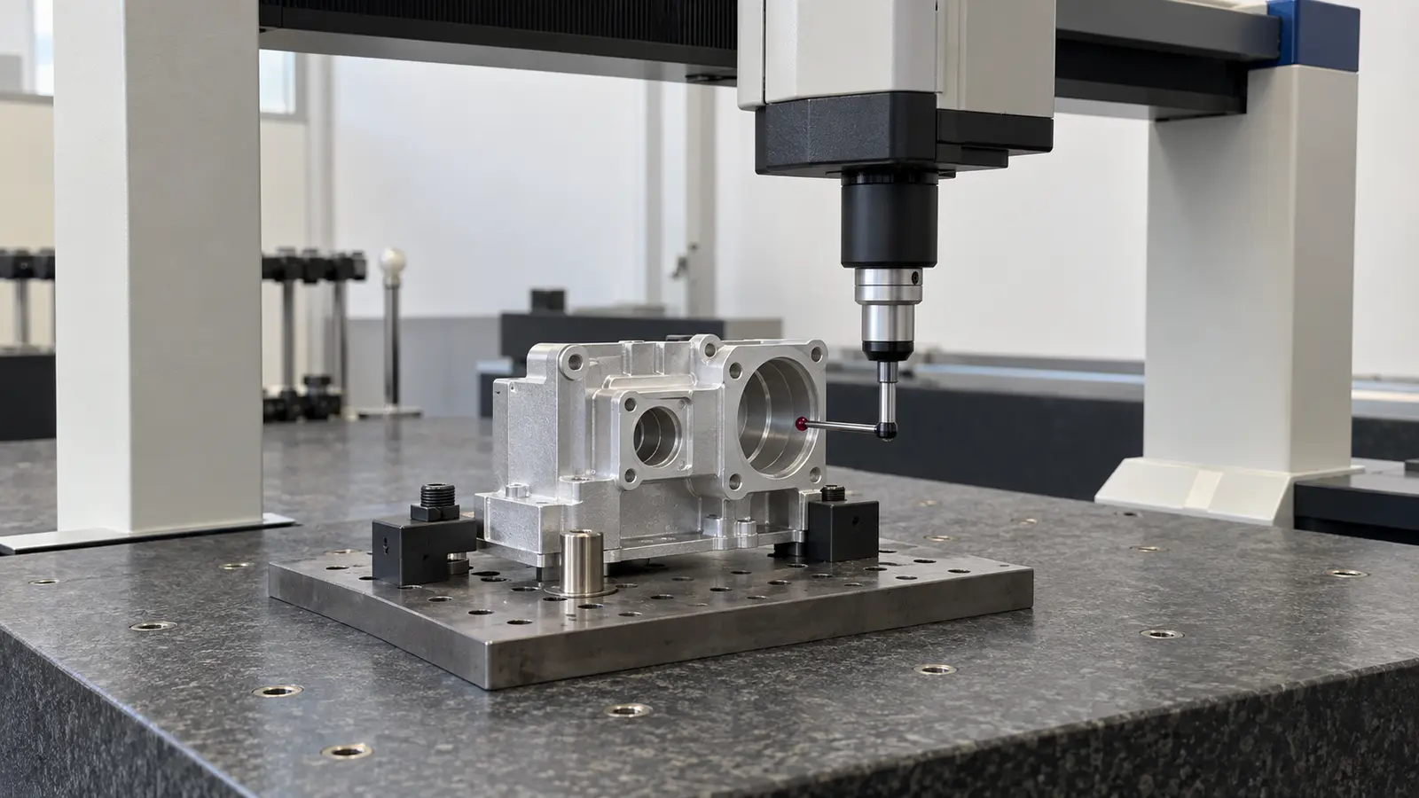
Meco can provide FAI, PPAP, CMM inspection and material traceability support. Confirm the deliverables for the order. Its CMM reference capability is ±0.002 mm, but measurement suitability and uncertainty still depend on the task.
Keep release decisions clear
An inspection report supports acceptance of the stated characteristics. It is not a declaration that a finished medical device is approved for use. Define who reviews the results, handles deviations and authorizes the next stage.
See Meco's medical equipment manufacturing capabilities for the manufacturing scope. Ask for the specific quality evidence needed rather than assuming a certification covers every requirement.
How Do You Choose a Prototype Manufacturing Partner?
Evaluate a supplier against the complete path from samples to the planned production route. Technical coverage, documentation and communication matter alongside price. Ask for evidence relevant to your component.
- Process fit. Review tool access, workholding, materials and finishing.
- Inspection fit. Confirm how critical dimensions and edges will be accepted.
- Traceability. Check lot identification and certificate handling.
- Transfer planning. Identify what will change between sample and production builds.
- Capacity. Discuss likely volumes and the controls needed at each level.
- Responsibility. Agree who approves drawings, deviations and changes.
Use the quote as a technical discussion
Provide the CAD model, drawing, quantity, material and finish. Identify the test purpose and critical-to-quality features, often shortened to CTQ. Include documentation requirements that affect scope.
A useful DFM review explains assumptions and flags open questions. If a tolerance changes, assess its effect on fit and testing before approving it. A lower price is useful only when the revised part still meets its requirements.
Integrated CNC machining, finishing and mechanical assembly can simplify coordination. Confirm each operation's scope and control rather than assuming that one supplier removes all handoff risks.
What Role Does Surface Finishing Play?
Finishing changes the surface that later tests and assemblies encounter. Define it alongside material and geometry. A polished, passivated or coated component may behave differently from an unfinished sample.
Common finishing considerations
- Passivation. Specify the treatment and acceptance needs where applicable to stainless steel parts.
- Electropolishing. Review material removal and its effect on edges and dimensions.
- Anodizing. Define coating and fit requirements for appropriate aluminum components.
- Cleaning. Identify residue, handling and packaging controls relevant to the part.
None of these operations automatically establishes sterility or biological safety. The device team should assess the complete finished configuration. Confirm specialist processes and evidence during quotation.
Include finishing in the sample plan
If a test depends on corrosion, friction or surface condition, an unfinished sample may not answer the production question. Record its limitations and plan the needed follow-up on representative parts.
Surface finishing services should be reviewed together with machining and inspection. After components are accepted, device-level assembly introduces further interfaces and controls. The companion medical device assembly guide covers that next step.
Discuss Your Medical Component Project
Share the drawing, build purpose and quality requirements. An engineer will review the manufacturing scope and advise on the next step.
- Engineering. DFM feedback before the build.
- Quality. IATF 16949:2016 certified manufacturing.
- Records. FAI, CMM and traceability support as agreed.
- Confidentiality. NDA available before files are shared.
References and sources
Regulatory sources reviewed on 2 October, 2026.
- U.S. Food and Drug Administration. Quality Management System Regulation. Updated February 2026.
- U.S. Food and Drug Administration. Technical Considerations for Additive Manufactured Medical Devices. Final guidance, December 2017.
- U.S. Food and Drug Administration. Biocompatibility Evaluation Endpoints by Device Category. Official assessment framework.
This article provides general manufacturing information. The responsible device manufacturer must determine applicable regulatory, quality and testing requirements for the device and target market. Supplier inspection records do not establish device approval.
